Noise reduction equipment for high-efficiency medical room

A medical room, high-efficiency technology, used in mechanical equipment, springs/shock absorbers, machines/brackets, etc., can solve the problems of cumbersome disassembly, inability to reduce vibration, poor noise suppression effect, etc., to reduce noise pollution, Improve heat dissipation performance and prevent high temperature burnout effect

Active Publication Date: 2020-08-28
陈慧
View PDF7 Cites 0 Cited by
  • Summary
  • Abstract
  • Description
  • Claims
  • Application Information

AI Technical Summary

Problems solved by technology

[0004] Although the existing noise reduction equipment for medical rooms is simple in structure and easy to operate, it has a single function. When installing the existing noise reduction equipment for medical rooms, it needs to drill holes and fix them with bolts, which may damage the medical equipment during installation. The internal parts, and when it needs to be disassembled, are also cumbersome and inconvenient to a certain extent. The existing noise reduction equipment for medical rooms cannot reduce and reduce the vibration generated by the operation of medical machines, resulting in poor noise suppression effect, and The internal parts of the medical machine vibrate for a long time are prone to loosening or damage, which has certain adverse effects. The existing noise reduction equipment used in the medical room dissipates heat between the medical machine and the noise reduction equipment, which is easy to make the components inside the medical machine Burning occurs, for this reason, we propose a high-efficiency noise reduction equipment for medical rooms

Method used


Image

  • Noise reduction equipment for high-efficiency medical room
  • Noise reduction equipment for high-efficiency medical room
  • Noise reduction equipment for high-efficiency medical room

Examples


Embodiment Construction

[0027] The following will clearly and completely describe the technical solutions in the embodiments of the present invention with reference to the accompanying drawings in the embodiments of the present invention. Obviously, the described embodiments are only some, not all, embodiments of the present invention. Based on the embodiments of the present invention, all other embodiments obtained by persons of ordinary skill in the art without making creative efforts belong to the protection scope of the present invention.

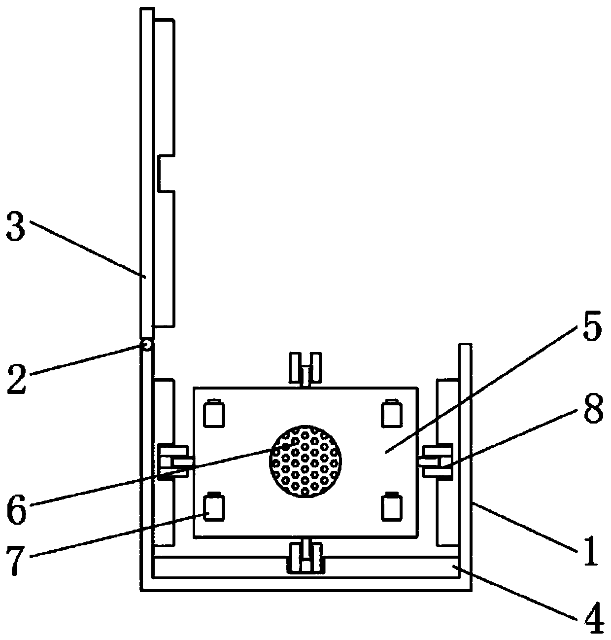
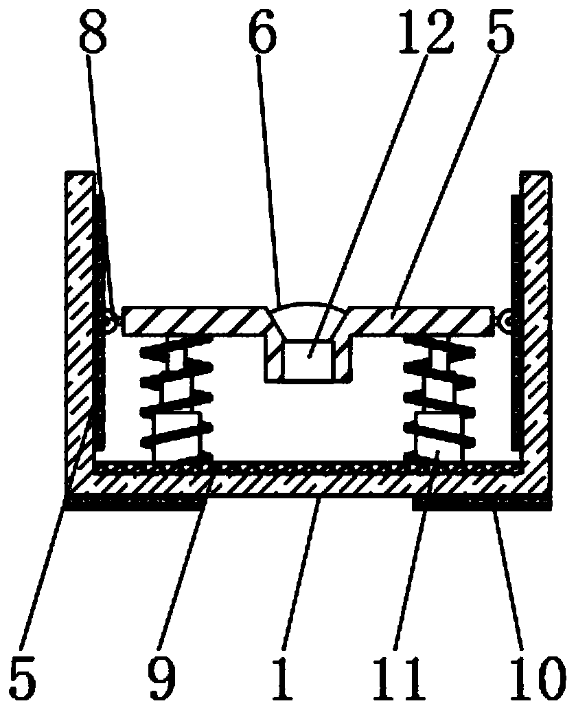
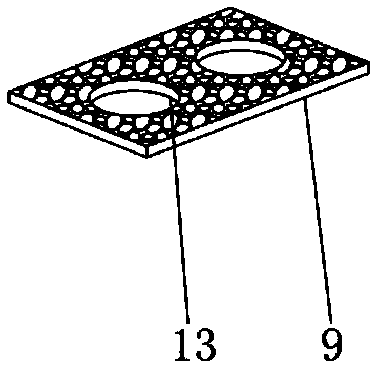
[0028] see Figure 1-8 , the present invention provides a technical solution: a high-efficiency noise reduction equipment for medical rooms, including a noise reduction equipment main body 1, the inner surface of the lower end of the noise reduction equipment main body 1 is fixedly installed with a second sound-absorbing cotton board 9 and a shock absorption mechanism 11 , the shock absorbing mechanism 11 is located on one side of the No. 2 sound-absorbing cot...


PUM


Abstract

The invention discloses high-efficiency noise reduction equipment for a treatment room. The high-efficiency noise reduction equipment for the treatment room comprises a noise reduction equipment body.The inner surface of the lower end of the noise reduction equipment body is fixedly provided with a second sound absorbing cotton plate and a damping mechanism. The damping mechanism is located on one side of the second sound absorbing cotton plate. The outer surface of the upper end of the damping mechanism is fixedly connected with an installation plate. According to the high-efficiency noise reduction equipment for the treatment room, by means of a connecting mechanism, when large-load equipment is installed, only a fixing groove fixed to the bottom of the large-load equipment needs to bealigned and inserted to bolts, during dismounting, a worker takes the fixing groove out of the bolts by pressing movable blocks, and compared with traditional screw fixation, operation is more convenient; by means of the damping mechanism, shake generated by equipment running can be reduced, and therefore noise generation can be reduced; and by means a heat dissipation mechanism, the heat dissipation effect of the equipment in a noise reduction device can be improved, the situation that high-temperature burning in the equipment is prevented, and using is facilitated for people.

Description

technical field [0001] The invention relates to the field of noise reduction equipment, in particular to a noise reduction equipment for high-efficiency medical rooms. Background technique [0002] Noise reduction equipment for medical rooms is a device that can reduce and eliminate the noise generated by medical machines inside the medical room. It has good noise effects and has been widely used. The functional requirements of noise reduction devices are also increasing. [0003] During use, the noise reduction equipment used in the medical room can complete the following forms of operations: by installing the noise equipment at the bottom of the medical machine, the vibration generated during the operation of the medical machine is reduced and reduced, and the noise is contained from the root, Thereby reducing noise pollution, which is beneficial to people's use. [0004] Although the existing noise reduction equipment for medical rooms is simple in structure and easy to...

Claims


Application Information

Patent Timeline
Patent Type & Authority Patents(China)
IPC IPC(8): F16M11/04F16M11/20F16F15/02F16F15/04
CPCF16F15/021F16F15/04F16M11/04F16M11/20
Inventor 陈慧
Owner 陈慧
Why Eureka
Try Eureka