Shooting equipment and shooting method
A technology for shooting equipment and shooting targets, which is applied to TVs, color TV parts, electrical components, etc., can solve problems such as application performance limitations of shooting equipment, and achieve the effect of improving application performance
- Summary
- Abstract
- Description
- Claims
- Application Information
AI Technical Summary
Problems solved by technology
Method used
Image
Examples
Embodiment 1
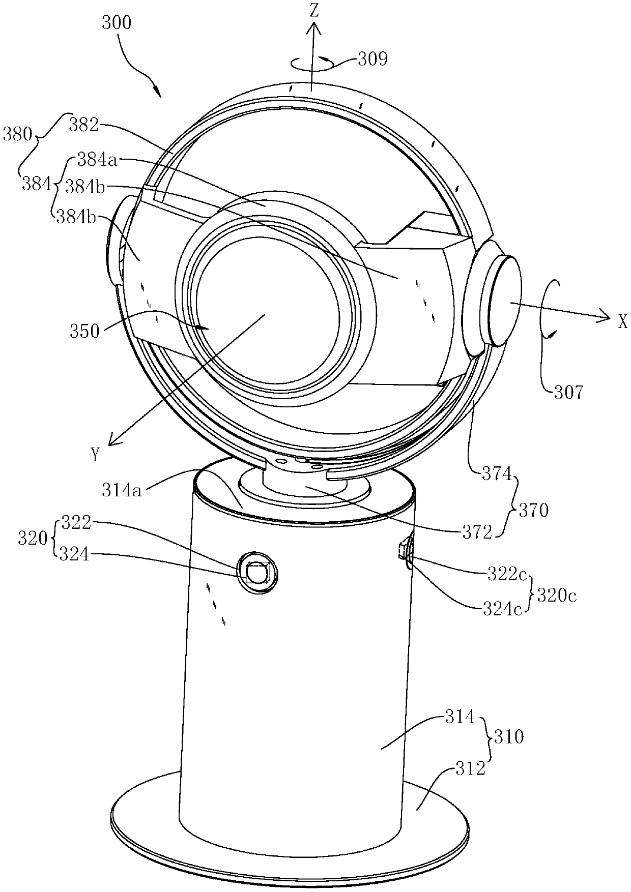
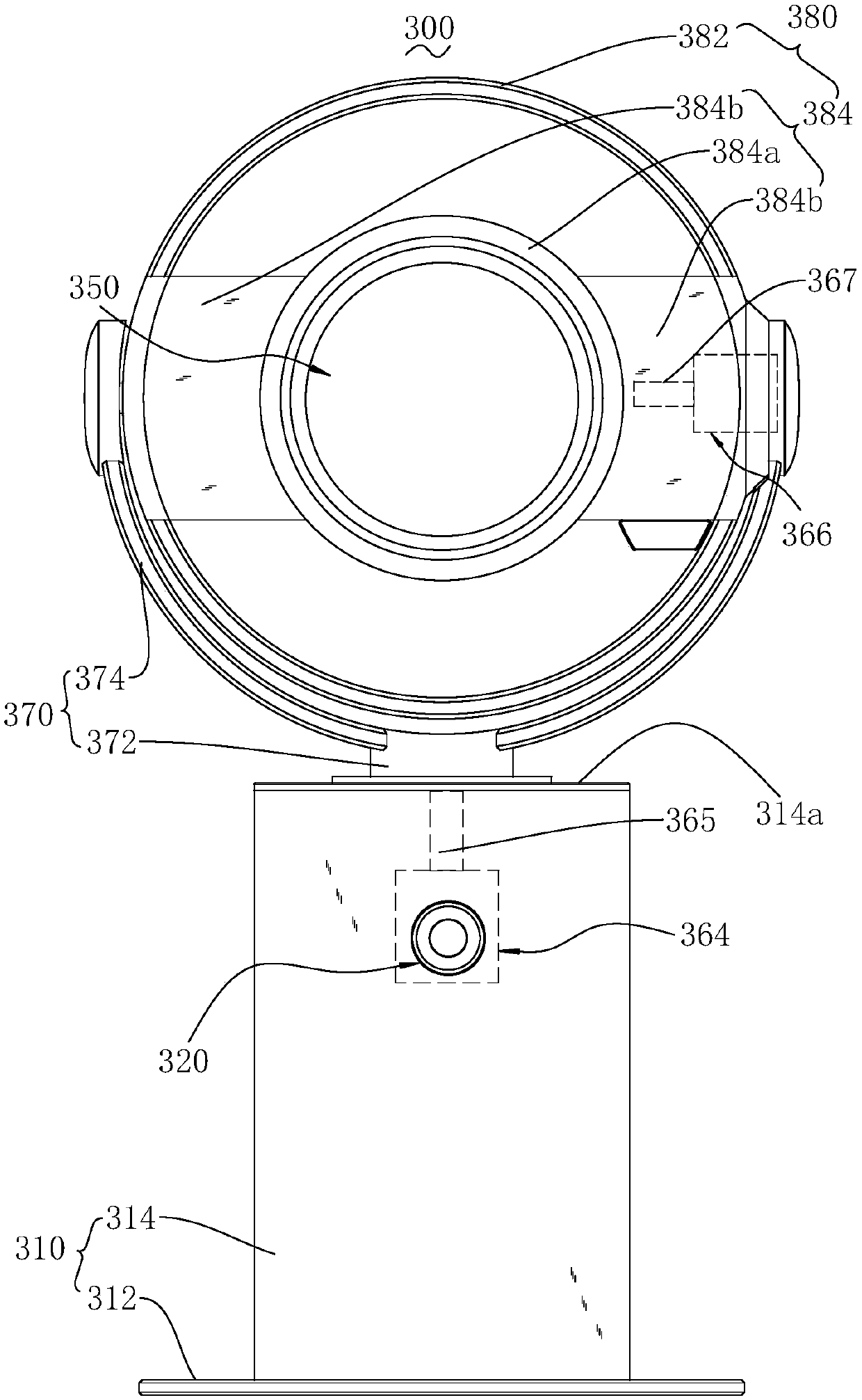
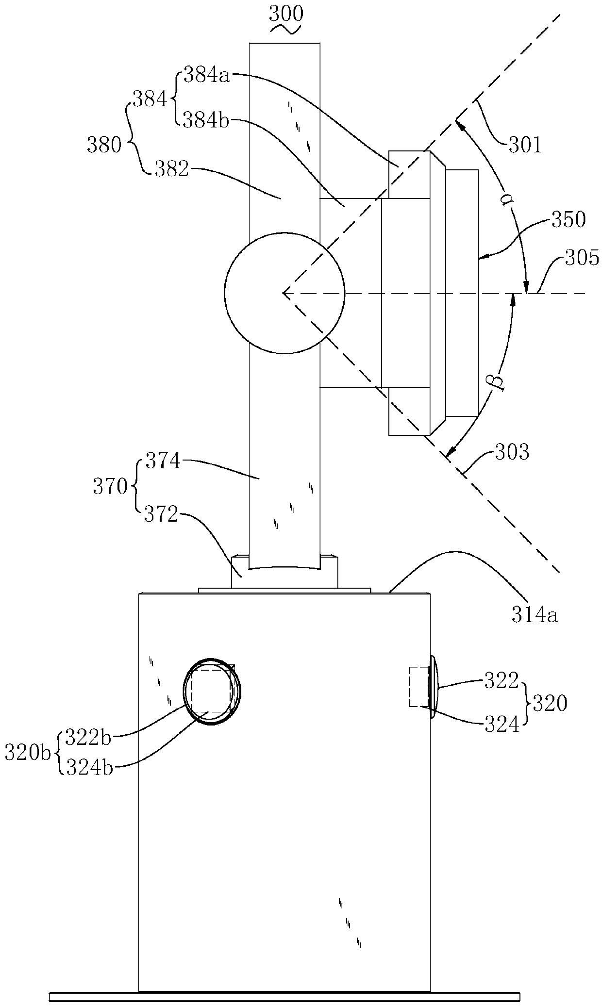
[0049] see Figure 1 to Figure 3 , which is a photographing device 300 provided in the present invention. As an optional implementation manner, the photographing device 300 includes a support base 310 , an optical lens 322 , an image sensor 324 and a camera 350 .
[0050] The support base 310 is used to support other components on the shooting device 300 . According to needs, the support seat 310 can also support other related components. The shape and structure of the support seat 310 only need to meet the corresponding support requirements. Optionally, the support seat 310 may be in the shape of a cylinder, a block, or the like. In this embodiment, in order to improve the stable supporting performance of the support base 310 and prevent the support base 310 from shaking, the support base 310 includes a bottom plate 312 and a support body 314 . The bottom plate 312 may be in the shape of a disc. The supporting body 314 is disposed on the bottom plate 312 . The supportin...
Embodiment 2
[0082] see Figure 9 , the invention also discloses a shooting method. The shooting method adopts the above-mentioned shooting device 300 to realize corresponding shooting. The shooting method includes the following steps:
[0083] S311: Monitor the current field of view.
[0084] Correspondingly, the current field of view can be monitored in real time through optical imaging elements such as the lens module 320 or the optical lens 322 , and optical imaging can be performed on objects entering the field of view.
[0085] S313: Identify whether the preset shooting target enters the current field of view?
[0086] Correspondingly, the identification unit 332 of the processor 330 may be used to identify whether the preset shooting target enters the field of view of the lens module 320 (or the optical lens 322 ).
[0087] When the preset shooting target does not enter the current field of view, continue to execute steps S311 and S313. That is, the lens module 320 (or the opti...
PUM
 Abstract
Description
Claims
Application Information
 - R&D
- Intellectual Property
- Life Sciences
- Materials
- Tech Scout
- Unparalleled Data Quality
- Higher Quality Content
- 60% Fewer Hallucinations
Browse by: Latest US Patents, China's latest patents, Technical Efficacy Thesaurus, Application Domain, Technology Topic, Popular Technical Reports.
© 2025 PatSnap. All rights reserved.Legal|Privacy policy|Modern Slavery Act Transparency Statement|Sitemap|About US| Contact US: help@patsnap.com


