
Camera

A camera and imaging system technology, applied in the field of cameras, can solve the problems of unfeasible assembly, poor operability, and adding light-isolation structures, etc., and achieve the effect of compact structure

Active Publication Date: 2019-03-26
ZHEJIANG DAHUA TECH CO LTD
View PDF5 Cites 0 Cited by
  • Summary
  • Abstract
  • Description
  • Claims
  • Application Information

AI Technical Summary

Problems solved by technology

[0003] The existing supplementary light methods mainly include the following three methods: first, the lens and the infrared light are relatively fixed on the same connector, and when the connector is adjusted, the lens and the infrared lamp are adjusted at the same time to ensure the lens supplementary light effect, but this The lens and the infrared lamp need to be set under the same dome cover. In this way, a light isolation structure needs to be added between the lens and the infrared lamp to prevent stray light from the lens from affecting the image quality. When the same lens is used at the same time, due to the The light isolation structure added on the lens will interfere with the dome cover, making the assembly unfeasible. For products with a hemispherical shape, this method 1 cannot be used for supplementary light; method 2, the lens and the infrared lamp are fixed on different structural parts. When adjusting the horizontal and vertical directions, the lens and the infrared light are on the same structural part, which can realize synchronous movement, but when adjusting the lens corridor mode, the position of the infrared light cannot be adjusted with the lens, and the second method is the same as the first method. The lens and the infrared lamp need to be set under the same dome cover, so it also has a series of disadvantages that need to increase the light isolation structure and increase the light isolation structure; the third method is that the lens and the infrared light are set under different dome covers, and the three-axis adjustment of the lens It is separated from the infrared light adjustment into two systems, the lens and the infrared light are adjusted separately to achieve supplementary light, but this method is poor in operability and affects customer experience

Method used


Image

  • Camera
  • Camera
  • Camera

Examples


Embodiment Construction

[0038] The following will clearly and completely describe the technical solutions in the embodiments of the present invention with reference to the accompanying drawings in the embodiments of the present invention. Obviously, the described embodiments are only some, not all, embodiments of the present invention. Based on the embodiments of the present invention, all other embodiments obtained by persons of ordinary skill in the art without making creative efforts belong to the protection scope of the present invention.

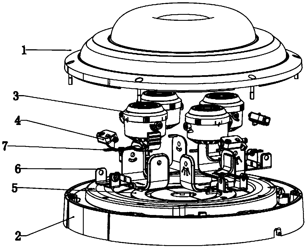
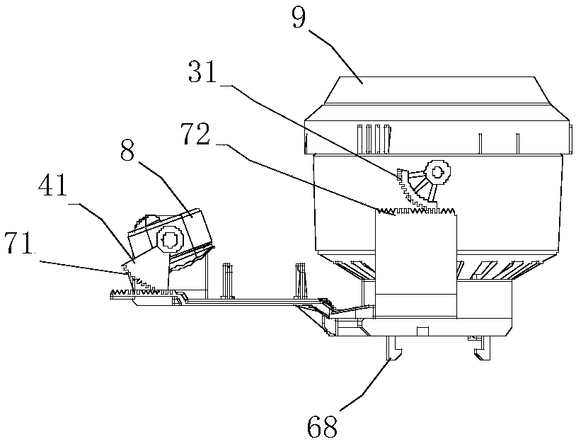
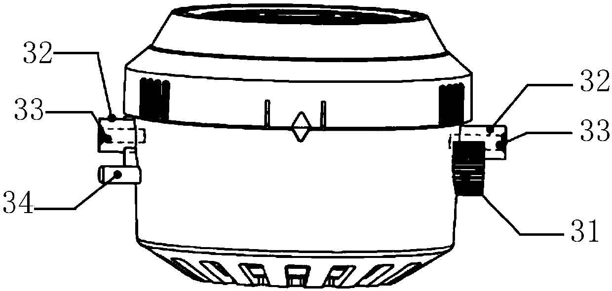
[0039] Such as figure 1 as well as figure 2 As shown, a camera includes a housing, an imaging system 9 and an infrared lamp 9 located in the housing, and also includes a slide rail 5, a slider bracket 6, a Z-shaped rack 7, a first rotating shaft, and carries the first imaging system 9. The assembly 3 and the second assembly 4 carrying the infrared lamp 9, the Z-shaped rack 7 includes an upper rack 72 and a lower rack 71, wherein:

[0040] The slide rail 5 i...


PUM


Abstract

The invention relates to the technical field of monitoring, and discloses a camera. The camera comprises an outer casing and an imaging system and an infrared lamp in the outer casing, and further comprises a slide rail, a slider bracket, a Z-shaped rack, a first rotating shaft, a first component carrying the imaging system and a second component carrying the infrared lamp. The slide rail is fixedto the bottom of the outer casing. The slider bracket slidably mounted to the slide rail. The Z-shaped rack is slidably mounted to the slider bracket, and the upper rack of the Z-shaped rack is engaged with the first component, and the lower rack of the Z-shaped rack is engaged with the second component. The first rotating shaft is perpendicular to the extending direction of the upper rack and perpendicular to the optical axis of the imaging system. The first component is rotatably mounted to the slider bracket around the first rotating shaft, and a positioning module locking the first component and the slider bracket while in a locking state is arranged between the first component and the slider bracket. The invention can synchronously adjust the imaging system and the infrared lamp to fill the imaging system, and is compact in structure.

Description

technical field [0001] The invention relates to the technical field of monitoring, in particular to a video camera. Background technique [0002] In the field of monitoring technology, night vision monitoring mainly uses infrared lights to emit infrared light to the monitoring area for supplementary light. The infrared light reflected back from the monitoring area is received by the lens, and after a series of processing, the image information is displayed on the final monitoring screen. [0003] The existing supplementary light methods mainly include the following three methods: Method 1, the lens and the infrared lamp are relatively fixed on the same connector, and when the connector is adjusted, the lens and the infrared lamp are adjusted at the same time to ensure the lens supplementary light effect, but this The lens and the infrared lamp need to be set under the same dome cover. In this way, a light isolation structure needs to be added between the lens and the infrare...

Claims


Application Information

Patent Timeline
IPC IPC(8): H04N5/225
CPCH04N23/50H04N23/56H04N23/57
Inventor 程仲点张小波李益伟
Owner ZHEJIANG DAHUA TECH CO LTD
Learn More