
Tool changing mold device for milling machine

A mold and milling machine technology, applied in the field of tool changing mold devices, can solve problems such as not satisfying users, affecting processing results, and eye-catching tool changing devices, and achieving the effect of solving movement problems

Active Publication Date: 2021-04-06
新昌县佛虑机械配件厂
View PDF6 Cites 0 Cited by
  • Summary
  • Abstract
  • Description
  • Claims
  • Application Information

AI Technical Summary

Problems solved by technology

[0002] A milling machine mainly refers to a machine tool that uses a milling cutter to process various surfaces of a workpiece. Usually, the milling cutter mainly uses rotational motion, and the movement of the workpiece and the milling cutter is a feed motion. It can process planes, grooves, and various Curved surfaces, gears, etc., although the existing milling machines can use the tool changer to change the tool, but most of the tool changers are too obtrusive, interfere with the user's sight, and affect the processing results, which do not meet the needs of the user

Method used


Image

  • Tool changing mold device for milling machine
  • Tool changing mold device for milling machine
  • Tool changing mold device for milling machine

Examples


Embodiment Construction

[0020] The following will clearly and completely describe the technical solutions in the embodiments of the present invention with reference to the accompanying drawings in the embodiments of the present invention. Obviously, the described embodiments are only some, not all, embodiments of the present invention. Based on the embodiments of the present invention, all other embodiments obtained by persons of ordinary skill in the art without making creative efforts belong to the protection scope of the present invention.

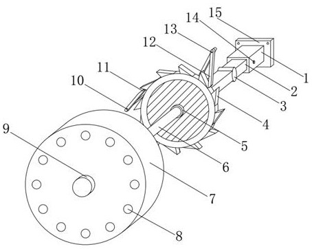
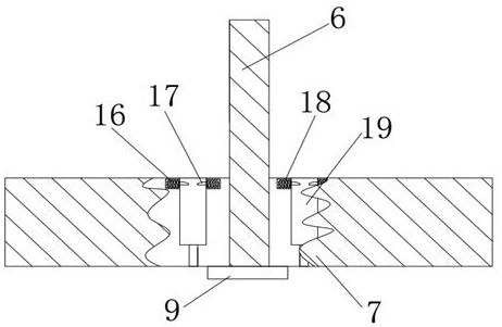
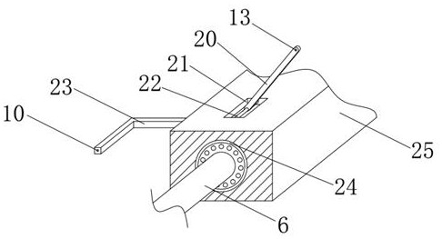
[0021] see Figure 1-4 , the present invention provides a technical solution: a tool change mold device for a milling machine, including a tool disc 7 and a main shaft 6, the center of the tool disc 7 is provided with a main shaft 6, and the inner cavity of the main shaft 6 and the tool disc 7 is interference fit , the cutter disc 7 can rotate with the main shaft 6, and the inner cavity around the cutter disc 7 is provided with a knife groove 19, the cutter is...


PUM


Abstract

The invention discloses a tool changing mold device for a milling machine. It includes a tool disc and a main shaft, the center of the tool disc is provided with a main shaft, the main shaft is in interference fit with the inner cavity of the tool disc, a second pawl is provided above the ratchet, and the gear teeth on the outer end of the ratchet are Corresponding to the second ratchet, and the second ratchet is engaged with the ratchet wheel, the second ratchet is connected to the swing rod through the second elastic ring, the first ratchet is provided on the left side of the ratchet wheel, the The teeth on the left side of the outer end of the ratchet correspond to the first pawl, and the first pawl meshes with the ratchet. The tool changer for milling machines, through the cooperation between the ratchet, the first pawl and the swing rod, It can drive the ratchet to do intermittent movement, which solves the movement problem of the whole mechanism. Through the cooperation between the hollow block, the universal wheel and the telescopic rod, it solves the problem of the impact of the tool change mechanism on the line of sight and meets the needs of users.

Description

technical field [0001] The invention relates to the technical field of milling machines, in particular to a tool changing mold device for milling machines. Background technique [0002] A milling machine mainly refers to a machine tool that uses a milling cutter to process various surfaces of a workpiece. Usually, the milling cutter mainly uses rotational motion, and the movement of the workpiece and the milling cutter is a feed motion. It can process planes, grooves, and various Curved surfaces, gears, etc., although the existing milling machines can use the tool changer to change the tool, but most of the tool changers are too obtrusive, interfere with the user's sight, and affect the processing results, which do not meet the user's needs. Contents of the invention [0003] The object of the present invention is to provide a tool changing mold device for milling machine, so as to solve the problems raised in the above-mentioned background technology. [0004] In order t...

Claims


Application Information

Patent Timeline
Patent Type & Authority Patents(China)
IPC IPC(8): B23Q3/157
CPCB23Q3/1554B23Q3/157
Inventor 孟令许张伟彬
Owner 新昌县佛虑机械配件厂
Learn More