
Bottom clearing plane capable of adjusting the position of plane tool

An adjustable, planing knife technology, applied in the field of woodworking planing, can solve the problems of different, uneven bottom cleaning, low efficiency, etc., and achieve the effect of good bottom cleaning effect, high bottom cleaning efficiency and wide application range.

Inactive Publication Date: 2019-03-29
湖州民阁木业有限公司
View PDF0 Cites 0 Cited by
  • Summary
  • Abstract
  • Description
  • Claims
  • Application Information

AI Technical Summary

Problems solved by technology

In the process of wood processing, it is often necessary to groove the wood, and the bottom surface of the grooves is usually uneven. For the uneven bottom of the groove, it is generally cleaned artificially with a bottom cleaning knife, but cleaning When using the bottom knife, due to the uneven force of people, the bottom cleaning effect is not ideal, the efficiency is low, and the direction of the groove is different, so it needs to be adjusted adaptively, and there is no such thing in the existing woodworking planer. A planer with bottom cleaning function

Method used


Image

  • Bottom clearing plane capable of adjusting the position of plane tool
  • Bottom clearing plane capable of adjusting the position of plane tool
  • Bottom clearing plane capable of adjusting the position of plane tool

Examples


Embodiment Construction

[0012] The present invention will be further described below in conjunction with the accompanying drawings and embodiments, but not as a basis for limiting the present invention.

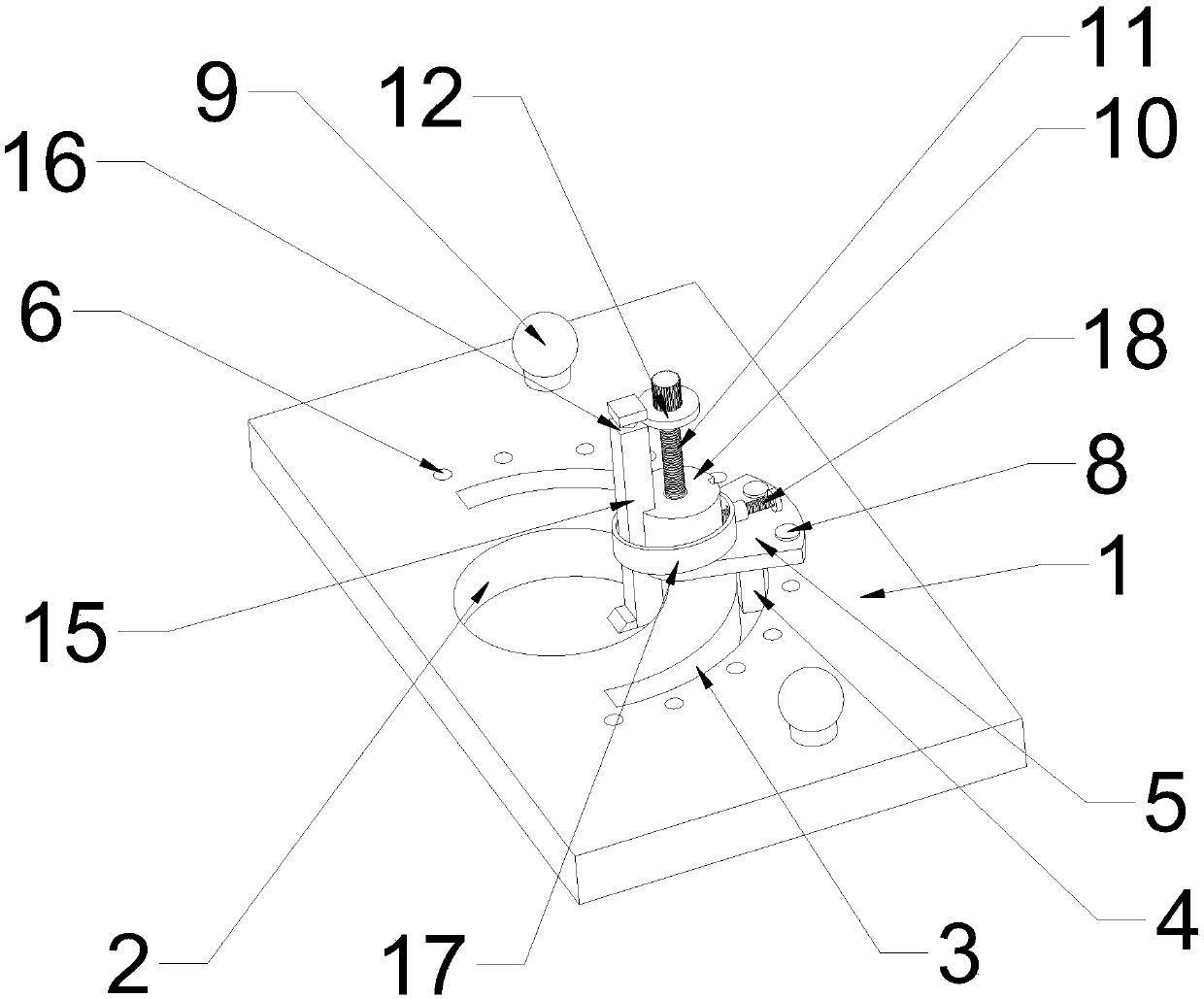
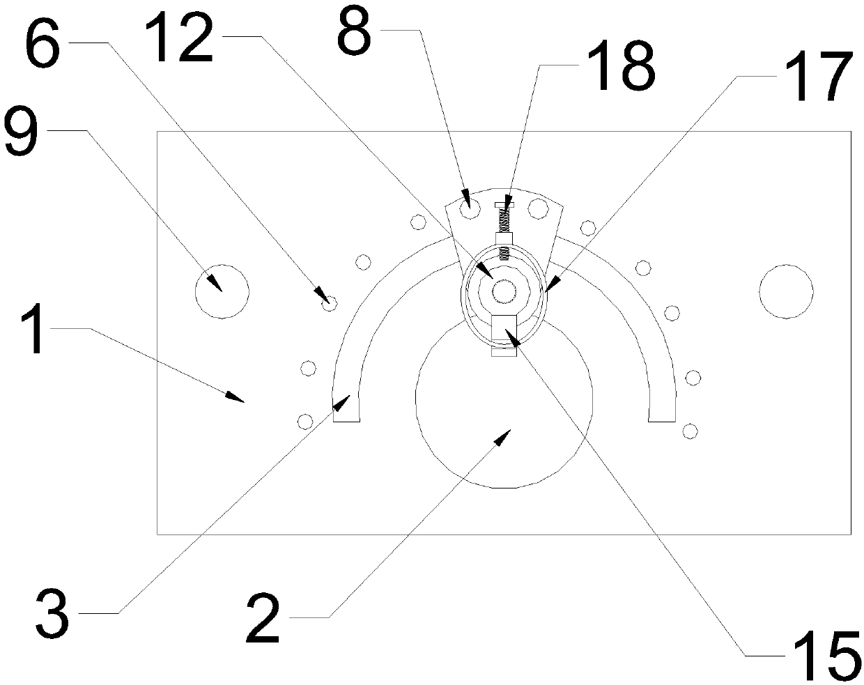
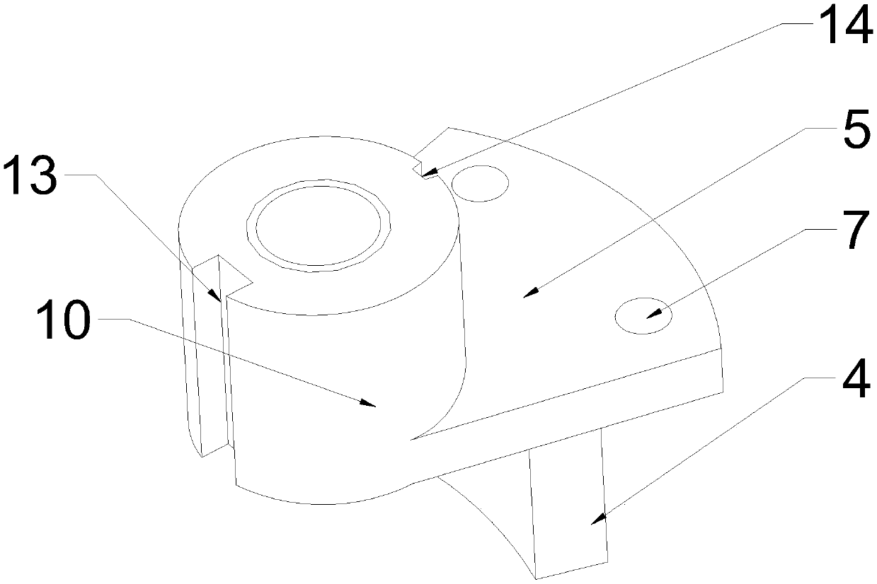
[0013] Example. A bottom-cleaning planer with adjustable planer position, which is composed of Figure 1 to Figure 3 As shown, including the planer body 1, the middle part of the planer body 1 is provided with a bottom-cleaning hole 2, and the outer side of the bottom-cleaning hole 2 is provided with an arc-shaped chute 3. Both sides of the chute 3 are provided with handles 9; the arc chute 3 is provided with an arc slider 4, and the arc chute 3 is connected with a fan-shaped fixing plate 5 through the arc slider 4, and the fan-shaped fixing plate 5 surface has a The countersunk hole 7, the countersunk hole 7 and the fixing hole 6 are connected by the fixing pin 8; the upper surface of the fan-shaped fixing plate 5 is provided with a fixing block 10, and the middle part of the fixing block 10 is pr...


PUM


Abstract

The invention discloses a bottom clearing plane capable of adjusting the position of a plane tool. The bottom clearing plane capable of adjusting the position of the plane tool comprises a plane body,a bottom clearing hole is formed in the middle of the plane body, and an arc-shaped sliding groove is formed in the outer side of the bottom clearing hole, a plurality of evenly-distributed fixing holes are formed in the outer side of the arc-shaped sliding groove, and handles are arranged on the two sides of the arc-shaped sliding groove; an arc-shaped sliding block is arranged in the arc-shapedsliding groove, the arc-shaped sliding groove is connected with a fan-shaped fixing plate through the arc-shaped sliding block, countersunk head holes are formed in the surface of the fan-shaped fixing plate, and the countersunk head holes are connected with the fixing holes through fixing pins; a fixing block body is arranged on the upper surface of the fan-shaped fixing plate, a first adjustingscrew rod is arranged in the middle of the fixing block body, a round pressing plate is arranged at the position, close to the top, of the first adjusting screw rod, and the position, close to the bottom cleaning hole, of the fixing block body is provided with a plane fixing groove; and an L-shaped plane tool is arranged in the plane tool fixing groove, and an annular groove for inserting the round pressing plate is formed in the top of the L-shaped plane tool, a locking ring is arranged outside the fixing block body, a second adjusting screw rod is connected to the side face of the locking ring, and the fixing block body and the L-shaped plane tool are fixed through the locking ring. According to the bottom cleaning plane, the bottom of a groove can be subjected to bottom cleaning treatment and is suitable for various pointing grooves.

Description

technical field [0001] The invention relates to the technical field of woodworking planers, in particular to a bottom-cleaning planer capable of adjusting the position of the planer. Background technique [0002] Woodworking planer is a kind of woodworking tool used for straightening, thinning, lightening and flattening the surface. It is widely used in the process of wood processing and is an indispensable and important tool in the woodworking industry. In the process of wood processing, it is often necessary to groove the wood, and the bottom surface of the grooves is usually uneven. For the uneven bottom of the groove, it is generally cleaned artificially with a bottom cleaning knife, but cleaning When using the bottom knife, due to the uneven force of people, the bottom cleaning effect is not ideal, the efficiency is low, and the direction of the groove is different, so it needs to be adjusted adaptively, and there is no such thing in the existing woodworking planer. A ...

Claims


Application Information

Patent Timeline
Patent Type & Authority Applications(China)
IPC IPC(8): B27G17/02
CPCB27G17/02
Inventor 方金泉
Owner 湖州民阁木业有限公司
Learn More