
Pay-off device preventing cable from being completely withdrawn and used for electric power construction

A technology of electric power construction and wire-laying device, which is applied in the direction of transportation and packaging, delivery of filamentous materials, thin material processing, etc., can solve difficult and dangerous problems, and achieve the effect of reducing internal humidity and promoting air circulation

Inactive Publication Date: 2019-03-29
南安市尚赢机械科技有限公司
View PDF15 Cites 0 Cited by
  • Summary
  • Abstract
  • Description
  • Claims
  • Application Information

AI Technical Summary

Problems solved by technology

[0003] At present, in the process of laying cables, the cable reels are often made to rotate, and then the workers pull the cables to move. When the cables move to a certain length, the workers need to cut off one end of the cables. Sometimes the gravity will cause the cable reel to rotate in reverse to withdraw the cable, causing the workers to take the cable from the cable reel again if they need to pull the wire again. This is not only difficult to work back and forth, but also more dangerous for high-altitude power construction operations.

Method used


Image

  • Pay-off device preventing cable from being completely withdrawn and used for electric power construction
  • Pay-off device preventing cable from being completely withdrawn and used for electric power construction
  • Pay-off device preventing cable from being completely withdrawn and used for electric power construction

Examples


Embodiment

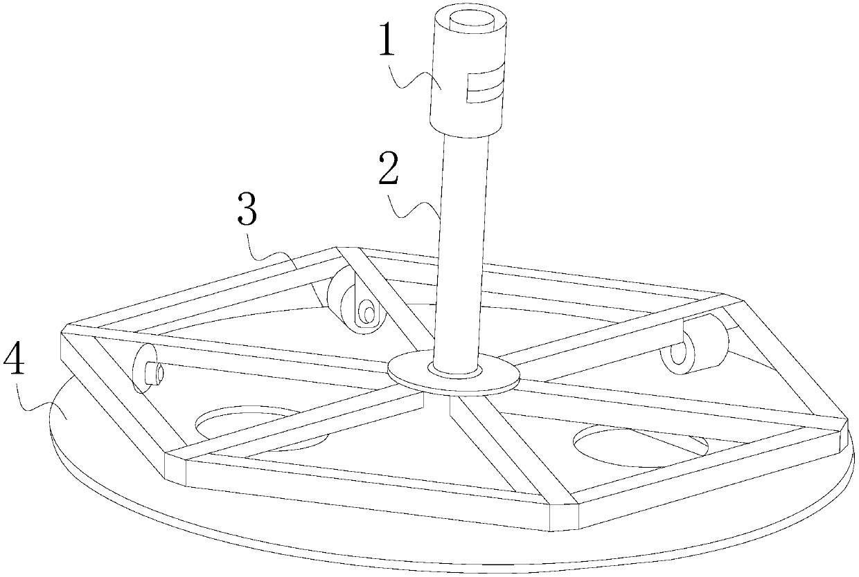
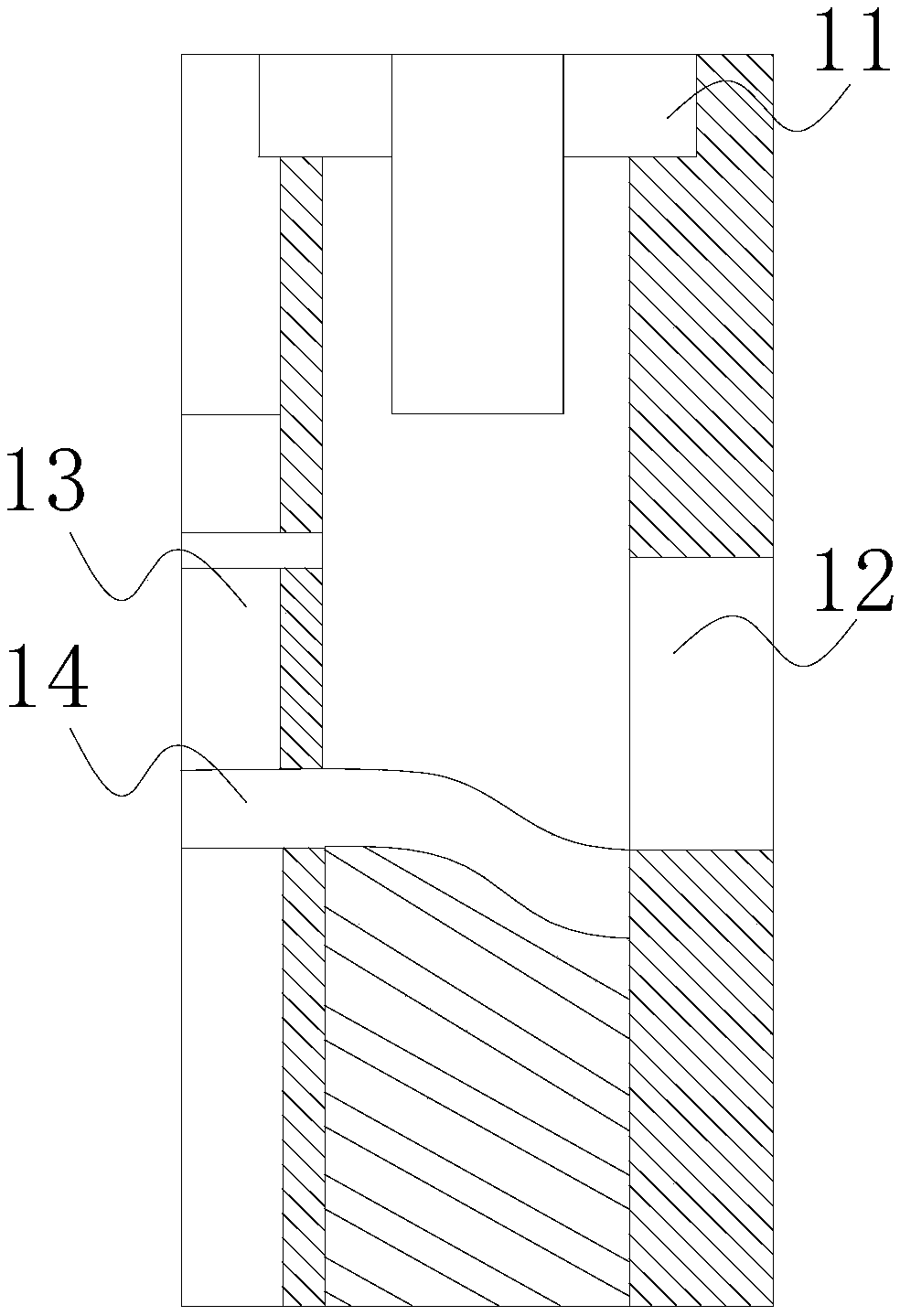
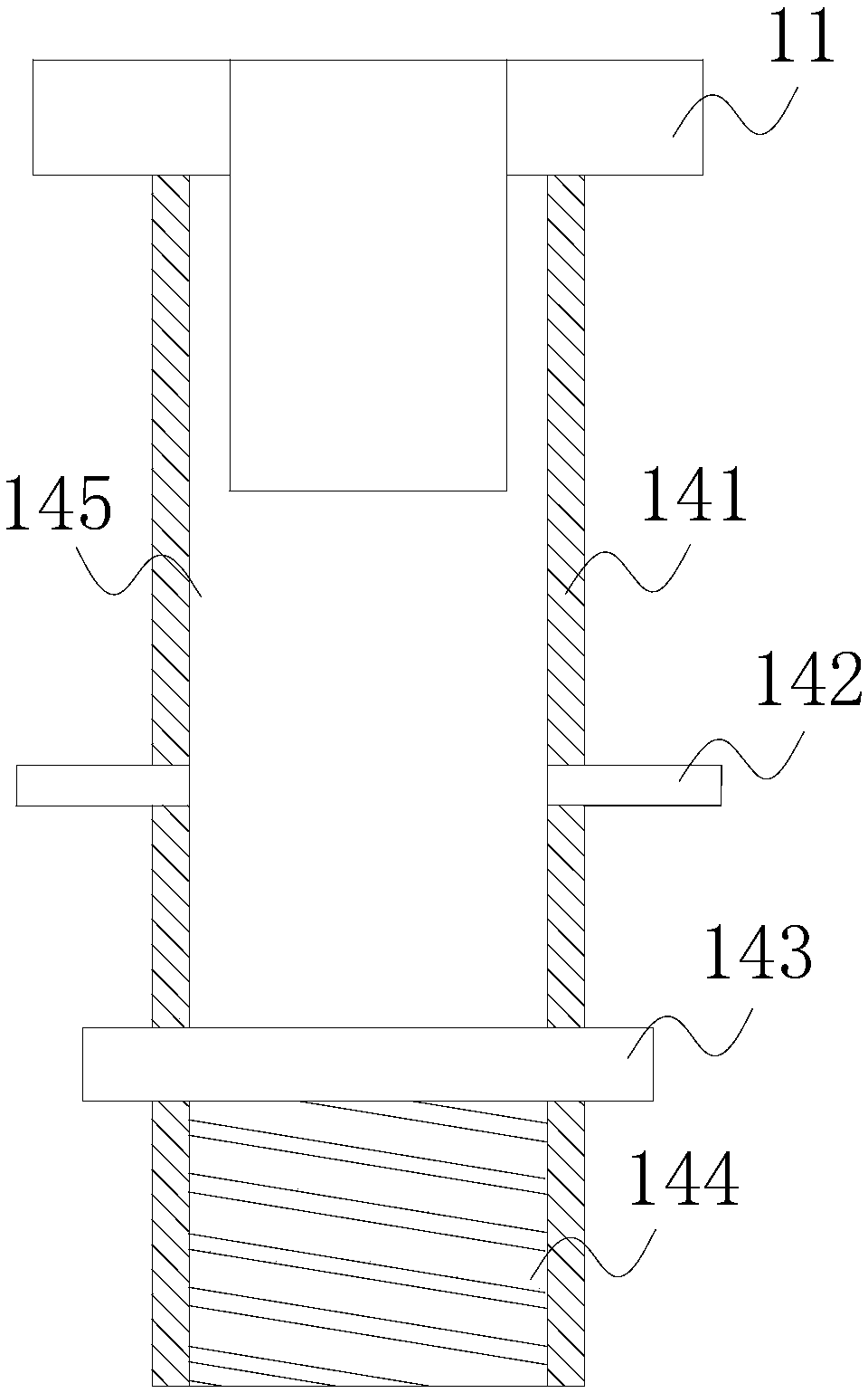
[0022] Such as Figure 1-Figure 4 As shown, the present invention provides a wire-releasing device for electric power construction that prevents the cables from being completely withdrawn. Its structure includes a fastening cabin 1, a wire take-up rod 2, a turntable 3, and a chassis 4. The chassis 4 is provided with a turntable 3, Wherein the center of the turntable 3 rotates vertically and is connected with the take-up rod 2, the four corners of the bottom end of the turntable 3 are respectively equipped with runners and matched with the chassis 4, and the top end of the take-up rod 2 is provided with a fastening compartment 1 and is an integrated structure, the interior of the fastening cabin 1 includes an upper jacking block 11, an inlet port 12, a movable opening 13, and an external force limiting mechanism 14, and the upper jacking block 11 and the external force limiting mechanism 14 In contrast, one end of the external force limiting mechanism 14 passes through the mova...


PUM


Abstract

The invention discloses a pay-off device preventing a cable from being completely withdrawn and used for electric power construction. The pay-off device preventing the cable from being completely withdrawn and used for electric power construction structurally comprises a buckling bin, a take-up rod, a rotating disk and a bottom disk; the rotating disk is arranged on the bottom disk, and the centerof the rotating disk is vertically and rotationally connected with the take-up rod; the four corners of the bottom end of the rotating disk are each provided with a rotating wheel and the rotating wheels are matched on the bottom disk; and the top end of the take-up rod is sleeved with the buckling bin and an integrated structure is achieved. According to the pay-off device preventing the cable from being completely withdrawn and used for electric power construction, an upper ejecting block and an external force limiting mechanism are jointly matched, a gap is reserved between a lower ejecting block and a cable inlet, and when the cable is inserted in from the cable inlet and pushed inwards, the gap is gradually expanded; when the pushing force is released, a spring bounces, the cable onthe lower ejecting block is ejected to be between the lower ejecting block and the upper ejecting block to be fixed, and therefore a role of fixing the cable is achieved; and thus when a cable tray rotates reversely to be withdrawn, the fixed cable is firmly fixed to the take-up rod, a worker is not needed to pick up the cable back and forth, and the using danger is further lowered while the operation difficulty is lowered.

Description

technical field [0001] The invention relates to a pay-off device, in particular to a pay-off device for electric power construction that prevents the cable from being completely withdrawn. Background technique [0002] Electric power engineering refers to engineering related to the production, transmission and distribution of electric energy. In a broad sense, it also includes engineering that uses electricity as power and energy in various fields. [0003] At present, in the process of laying cables, the cable reels are often made to rotate, and then the workers pull the cables to move. When the cables move to a certain length, the workers need to cut off one end of the cables. Sometimes the gravity will cause the cable reel to rotate in reverse to withdraw the cable, causing the workers to take the cable from the cable reel again if they need to pull the wire again. This is not only difficult to work back and forth, but also more dangerous for high-altitude power construct...

Claims


Application Information

Patent Timeline
Patent Type & Authority Applications(China)
IPC IPC(8): B65H49/20B65H75/28
CPCB65H49/20B65H75/285B65H2701/34
Inventor 陈诗庄
Owner 南安市尚赢机械科技有限公司
Learn More