
Annular beam device and method for adjusting local flow velocity of pipeline

A technology to adjust the pipeline and flow rate, which is applied in the direction of valve device, valve details, valve shell structure, etc., can solve the problem that the steam flow rate is difficult to adjust in time, and achieve the effect of easy disassembly and assembly

Active Publication Date: 2021-12-31
XIAN XIRE ENERGY SAVING TECH +1
View PDF6 Cites 0 Cited by
  • Summary
  • Abstract
  • Description
  • Claims
  • Application Information

AI Technical Summary

Problems solved by technology

[0004] The purpose of the present invention is to overcome the above-mentioned shortcomings of the prior art, and provide an annular beam flow device and method for adjusting the local flow velocity of the pipeline, so as to solve the shortage of the existing heating system and the problem that the steam flow velocity is difficult to adjust in time

Method used


Image

  • Annular beam device and method for adjusting local flow velocity of pipeline
  • Annular beam device and method for adjusting local flow velocity of pipeline
  • Annular beam device and method for adjusting local flow velocity of pipeline

Examples


Embodiment 1

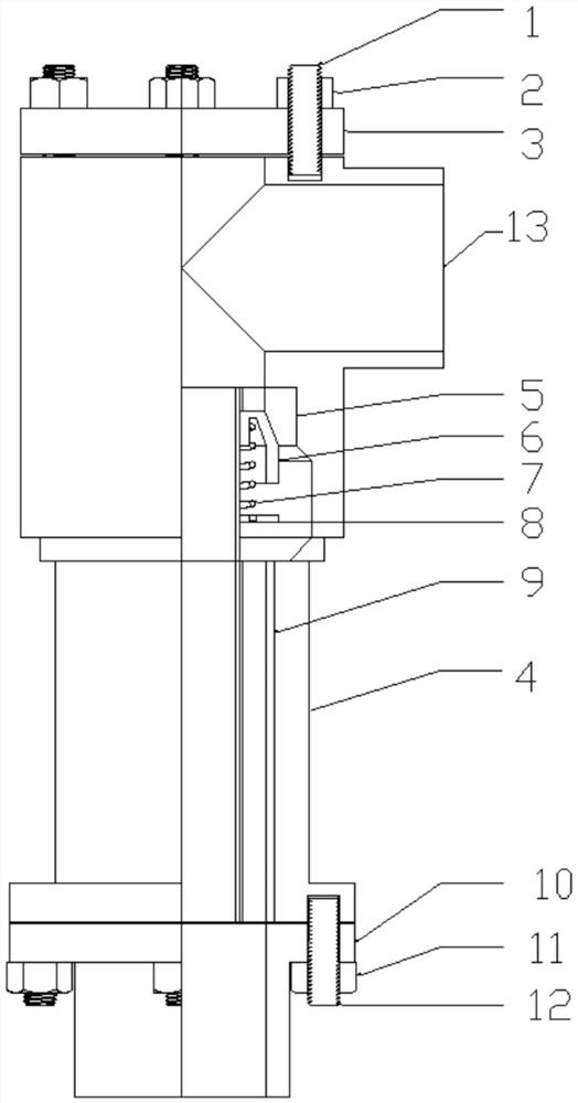
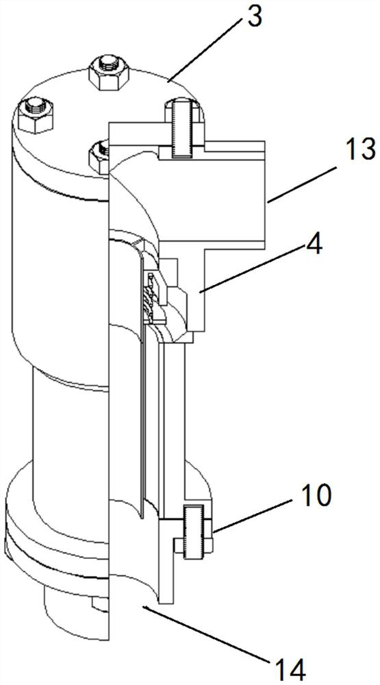
[0044] see figure 1 , figure 2 , image 3 and Figure 4 , the side wall of the valve body 4 is provided with a working fluid inlet 13, the axis of the working fluid inlet 13 is perpendicular to the axis of the valve body 4, and the inside of the valve body 4 is sequentially provided with a splitter sleeve 5 and a double flow channel from top to bottom. The upper end surface of the sleeve 9 and the splitter sleeve 5 is below the inlet 13 of the working fluid.

[0045] see Figure 5 and Figure 6 , the splitter sleeve 5 and the valve body 4 are coaxial, the splitter sleeve 5 includes a coaxial inner ring 501 and an outer ring 502, the inner ring 501 is arranged in the outer ring 502, and the two do not touch; the inner ring 501 and the outer ring 502 are connected by the first connecting plate 504, the first connecting plate 504 is equally divided along the circumference of the outer ring 502, the first connecting plate 504 is arranged along the length direction of the val...

Embodiment 2

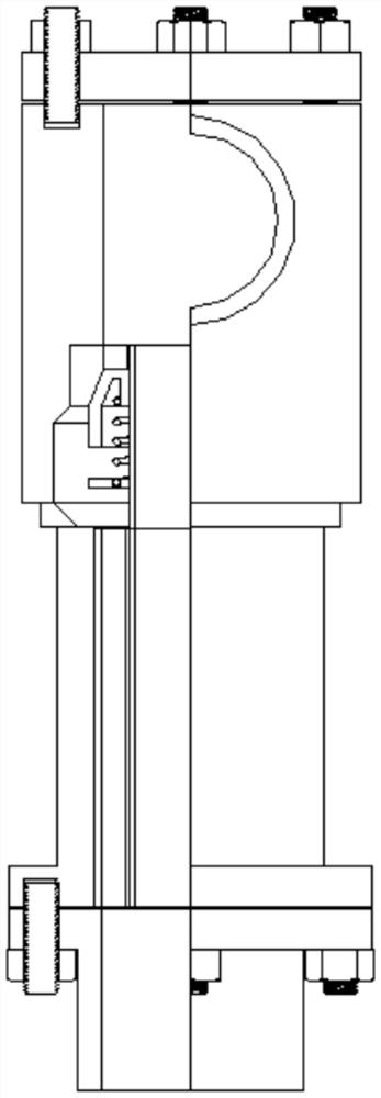
[0050] see Figure 7 and Figure 8 , the entire valve of this embodiment is a straight-through type, the working fluid inlet 13 is set on the valve cover 3 at the inlet end, and the working fluid inlet 13 and the valve body 4 are coaxial.

[0051] The working method of above-mentioned two embodiments is:

[0052] When the flow rate of the working fluid is lower than the set value, the beam ring 6 is pressed upward by the spring 7, and the first slope 503 and the second slope 601 are sealed against each other under the support force of the spring 7 and the magnetic force; The inlet 13 enters the valve body 4, the working medium passes through the inner ring 501, passes through the inner sleeve 901 of the double-channel sleeve 9, and flows out from the working medium outlet 14;

[0053] When the flow rate of the working fluid is greater than the set value, the thrust given by the working fluid to the beam ring 6 from above overcomes the magnetic force and the supporting force ...


PUM


Abstract

The invention discloses an annular beam device and method for adjusting the local flow velocity of a pipeline. The device adopts a shunting partition plate sleeve and a beam ring to adjust the through-flow area of the pipeline, and builds an inner-layer through-flow space and an outer-layer through-flow space under the assistance of a double-channel sleeve, and the inner-layer through-flow space and the outer-layer through-flow space are independent from each other; the shunting partition plate sleeve is sleeved with the beam ring, a spring is installed on the lower portion of the beam ring, and a limiting supporting ring is installed below the spring and used for supporting and limiting the spring and the beam ring; the limiting supporting ring is connected with the shunting partition plate sleeve; the spring is used for adjusting opening and closing of the beam ring; and the beam ring and a shunting partition plate have magnetism and can give a proper acting force to assist in sealing the outer-layer through-flow space at a low flow velocity and opening the outer-layer through-flow space at a high flow velocity.

Description

technical field [0001] The invention belongs to the technical field of valves, and in particular relates to an annular beam flow device and method for adjusting local flow velocity of a pipeline. Background technique [0002] In eligible large and medium-sized cities, moderately build large-scale thermal power units and encourage the construction of back-pressure thermal power units; in small and medium-sized cities and industrial parks with concentrated heat loads, give priority to the construction of back-pressure thermal power units; encourage the development of combined heating, power, and cooling. [0003] In recent years, the installed capacity of wind power and photovoltaic new energy has continued to increase, and at the same time, the overall power receiving scale has also increased significantly, and the contradiction of power grid peak regulation has become increasingly prominent. In order to alleviate the contradictions of the gap in the adjustment gap and improv...

Claims


Application Information

Patent Timeline
Patent Type & Authority Applications(China)
IPC IPC(8): F16K17/24F16K27/08F16K27/00
CPCF16K17/24F16K27/08F16K27/00
Inventor 郑天帅余小兵王伟郭中旭刘学亮王东晔杨利刘永林李昊
Owner XIAN XIRE ENERGY SAVING TECH
Learn More