
A wall-mounted LED light that is easy to adjust the light angle

A technology of LED lights and lighting angles, which is applied to the components of lighting devices, semiconductor devices of light-emitting elements, light sources, etc., which can solve the problems that the lighting angle cannot be adjusted and the lighting angle is fixed, so as to avoid the lighting angle and ensure the light emission The effect of brightness and luminous uniformity

Inactive Publication Date: 2021-09-24
江门市金仕达照明电器有限公司
View PDF14 Cites 0 Cited by
  • Summary
  • Abstract
  • Description
  • Claims
  • Application Information

AI Technical Summary

Problems solved by technology

However, its light angle is fixed, so that it cannot adjust the light angle according to the user's needs.

Method used


Image

  • A wall-mounted LED light that is easy to adjust the light angle
  • A wall-mounted LED light that is easy to adjust the light angle
  • A wall-mounted LED light that is easy to adjust the light angle

Examples


Embodiment 1

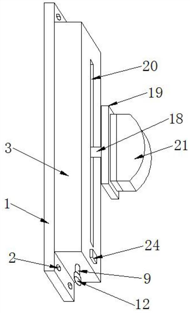
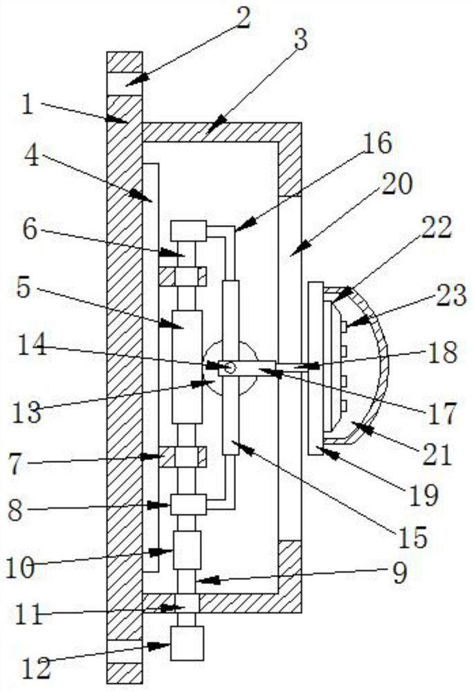
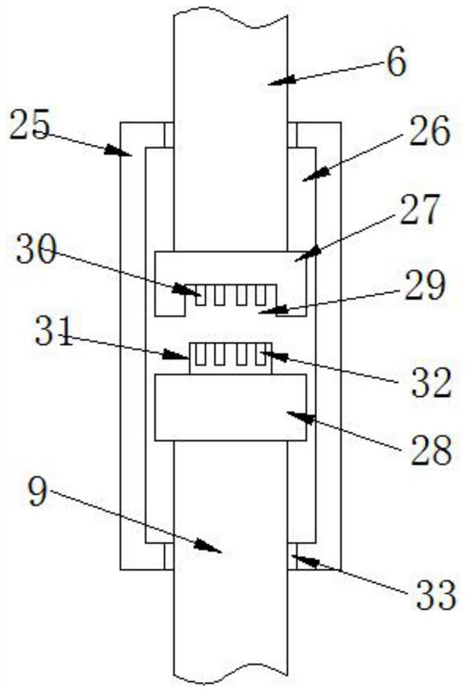
[0029] Embodiment one, such as Figure 1-2 As shown, a wall-mounted LED lamp for adjusting the illumination angle according to an embodiment of the present invention includes a fixed base 1, a housing 3 is installed on one side of the fixed base 1, and a housing 3 is installed inside the housing 3. An adjustment mechanism, the adjustment mechanism includes a fixed plate 4, and the fixed plate 4 is fixed on the fixed base 1 by several bolts, a worm 5 is installed on one side of the fixed plate 4, and the two ends of the worm 5 Rotating shafts 6 are installed at both ends, and bearing blocks 7 matching with the rotating shafts 6 are installed at both ends of the worm 5, and one side of the bearing blocks 7 is fixed on the fixed plate 4 One end of the rotating shaft 6 and the end far away from the worm 5 are provided with a matching ring 8, and one end of the rotating shaft 6 at the bottom of the worm 5 is equipped with a rotating rod-9, and The rotating rod one 9 is connected t...

Embodiment 2

[0030] Embodiment two, such as Figure 1-2 As shown, the fixed base 1 is provided with several threaded holes 2, and the threaded holes 2 are all located at the corners of the fixed base 1. By being provided with several threaded holes 2, the fixed base 1 The installation has brought great convenience.

[0031] Embodiment two, such as Figure 1-2 As shown, the bottom of the housing 3 is penetratingly provided with a through hole 11 matched with the rotating rod 9, through which the through hole 11 is provided, thereby providing an effective guarantee for the rotation of the rotating rod 9.

Embodiment 3

[0032] Embodiment three, such as Figure 1-2 As shown, one side of the housing 3 is provided with an open slot 20 matched with the support rod 18 , through the setting of the open slot 20 , an effective guarantee is provided for the adjustment of the support rod 18 .


PUM


Abstract

The invention discloses a wall-mounted LED lamp which is convenient for adjusting the illumination angle. A number of bolts are fixed on the fixed base, a worm is installed on one side of the fixed plate, a rotating shaft is installed on both ends of the worm, and a bearing seat matching the rotating shaft is installed on both ends of the worm, and one of the bearing seats Both sides are fixed on the fixed plate, one end of the rotating shaft and the end away from the worm are all sleeved with a matching ring, one end of the rotating shaft at the bottom of the worm is equipped with a rotating rod one, and the connecting rod one and the rotating shaft are connected by a connecting mechanism. Beneficial effects: the present invention is provided with an adjustment mechanism, so that it can adjust the illumination angle of the LED lamp according to the user's use requirements, so that it can better provide convenience for the user's lighting.

Description

technical field [0001] The invention relates to the technical field of LED lamps, in particular to a wall-mounted LED lamp for adjusting the illumination angle. Background technique [0002] In the field of lighting, LED energy-saving lamps, as a new type of lighting source, are favored by the majority of the people and strongly supported by the country for their remarkable characteristics of energy saving, health, environmental protection and long life. At present, LED wall-mounted lamps mainly use screws to fix the lamp base on the wall to achieve wall-mounting. This method of wall-mounted mounting is cumbersome and time-consuming to disassemble and assemble. [0003] Patent No. CN201720728055.3 discloses a wall-mounted LED lamp, which uses a screw to insert a through hole and screw it into the screw hole, turn the handle to make the cam compress the support plate, thereby fixing the support plate on the wall, Connect the card slot to the support plate, so that the lamp h...

Claims


Application Information

Patent Timeline
Patent Type & Authority Patents(China)
IPC IPC(8): F21S8/00F21V21/14F21V21/02F21V3/12F21Y115/10
CPCF21S8/033F21V21/02F21V21/14F21Y2115/10F21V3/12
Inventor 陈玉燕
Owner 江门市金仕达照明电器有限公司
Learn More