Sterilization and disinfection device, display device and lamp box
A sterilizing and disinfecting device and a sterilizing and sterilizing technology, applied to display devices, illuminated marks, light guides, etc., can solve the problems of complex structure and single function of the equipment, and achieve significant economic benefits, wide applicability, and low cost.
- Summary
- Abstract
- Description
- Claims
- Application Information
AI Technical Summary
Problems solved by technology
Method used
Image

Examples
Embodiment 1
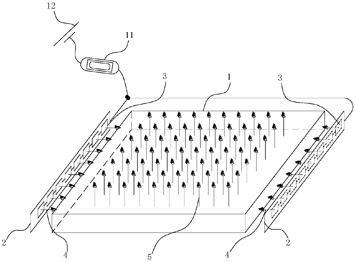
[0036] Please refer to figure 2 , in the first embodiment, the light guide plate 1 is rectangular or square, with a first side 21, a second side 22, a third side 23, and a fourth side 24, and the two ends of the first side 21 are respectively connected to the second side The two sides 22 and the fourth side 24 are adjacent at one end, the two ends of the third side 23 are adjacent to the other end of the second side 22 and the fourth side 24, and the first side 21 is parallel to the third side 23 , The second side 22 is parallel to the fourth side 24 .
[0037] The first line light source 6 is located on the first side 21 and the third side 23 respectively, and the second line light source 7 is located on the second side 22 and the fourth side 24 respectively.
[0038] Specifically, the substrate 2 is set towards the first side 21, the second side 22, the third side 23, and the fourth side 24 respectively, and the first light source 8 is respectively installed on the first s...
Embodiment 2
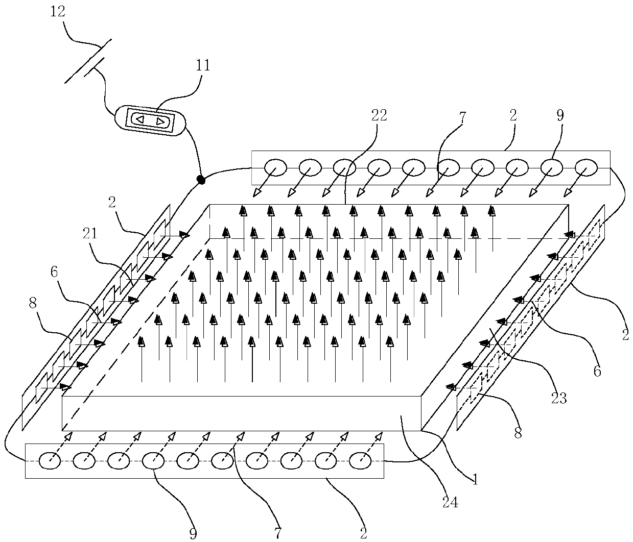
[0043] Please refer to Figure 6 , in this embodiment, the first side 21 is provided with the first line light source 6 and the second line light source 7 arranged in parallel, and the third side 23 is correspondingly provided with the first line light source 6 and the second line light source 7 arranged in parallel; in other implementations In an example, the first line light source 6 and the second line light source 7 arranged in parallel are arranged on the second side 22 , and the first line light source 6 and the second line light source 7 arranged in parallel are arranged on the fourth side 24 correspondingly.
[0044] In this embodiment, by setting the first line light source 6 and the second line light source 7 arranged in parallel up and down on a pair of sides of the light guide plate 1, the effect achieved by the first embodiment can also be achieved, and the circuit principle is the same as that of the first embodiment. I won't repeat them here. Compared with Embo...
Embodiment 3
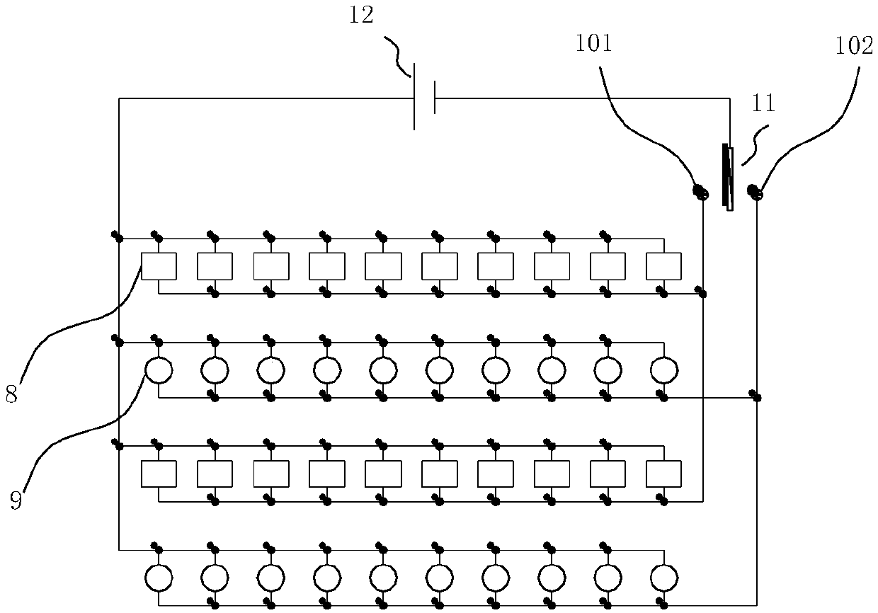
[0048] Please refer to Figure 7 , in this embodiment, the first side 21 is provided with staggered first line light sources 6 and second line light sources 7, and the third side 23 is correspondingly provided with staggered first line light sources 6 and second line light sources 7; in other implementations In the example, the first line light source 6 and the second line light source 7 arranged in a staggered arrangement are arranged on the second side 22 , and the first line light source 6 and the second line light source 7 arranged in a staggered arrangement are correspondingly arranged on the fourth side 24 .
[0049] Same as Embodiment 2, Embodiment 3 can also realize the first line light source 6 and the second line light source 7 arranged in a staggered arrangement on a pair of sides of the light guide plate 1 respectively, so as to achieve the effect of Embodiment 1. The circuit principle is as follows Figure 8 As shown, the light-emitting devices corresponding to th...
PUM
 Abstract
Description
Claims
Application Information
 - R&D
- Intellectual Property
- Life Sciences
- Materials
- Tech Scout
- Unparalleled Data Quality
- Higher Quality Content
- 60% Fewer Hallucinations
Browse by: Latest US Patents, China's latest patents, Technical Efficacy Thesaurus, Application Domain, Technology Topic, Popular Technical Reports.
© 2025 PatSnap. All rights reserved.Legal|Privacy policy|Modern Slavery Act Transparency Statement|Sitemap|About US| Contact US: help@patsnap.com