Calibration method and device

A calibration method and technology of a calibration device are applied in image data processing, complex mathematical operations, instruments, etc., and can solve problems such as display errors of three-dimensional virtual scenes and spatial light vector differences of projection display devices.

Active Publication Date: 2019-03-29
SHENZHEN SKYWORTH NEW WORLD TECH CO LTD
View PDF5 Cites 3 Cited by
  • Summary
  • Abstract
  • Description
  • Claims
  • Application Information

AI Technical Summary

Problems solved by technology

[0003] Due to errors in processing and assembly, the spatial light vector of the actual beam emitted by the projection display device will be different from the theoretical one

Method used


Image

  • Calibration method and device
  • Calibration method and device
  • Calibration method and device

Examples


Embodiment Construction

[0058] The following will clearly and completely describe the technical solutions in the embodiments of the present invention with reference to the drawings in the embodiments of the present invention. Apparently, the described embodiments are only some of the embodiments of the present invention, not all of them. The components of the embodiments of the invention generally described and illustrated in the figures herein may be arranged and designed in a variety of different configurations.

[0059] Accordingly, the following detailed description of the embodiments of the invention provided in the accompanying drawings is not intended to limit the scope of the claimed invention, but merely represents selected embodiments of the invention. Based on the embodiments of the present invention, all other embodiments obtained by those skilled in the art without making creative efforts belong to the protection scope of the present invention.

[0060] It should be noted that like nume...


PUM


Abstract

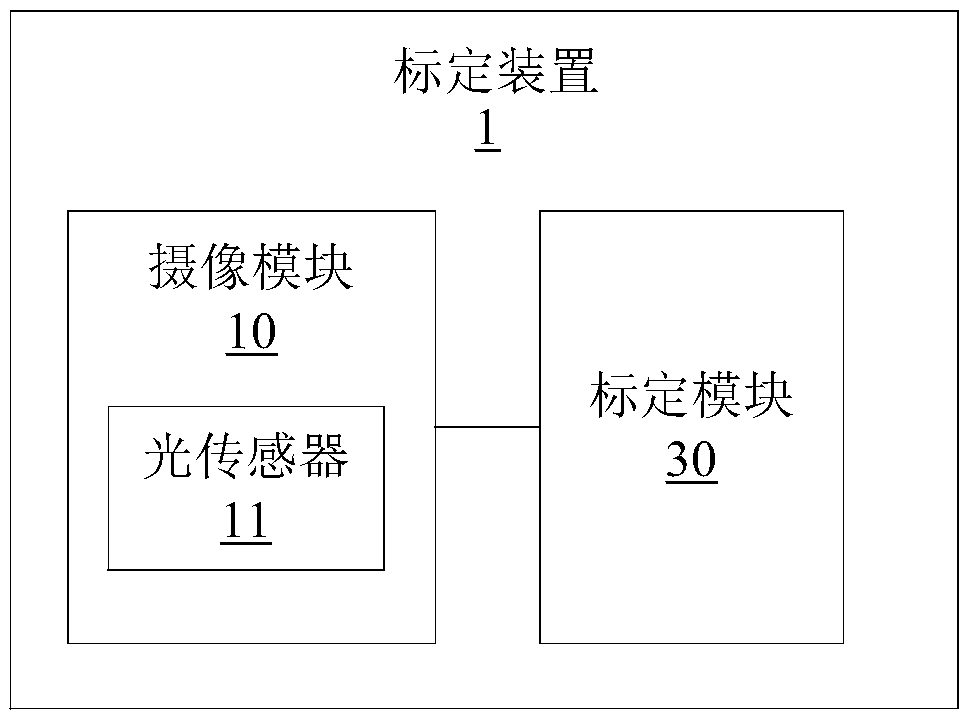
The invention relates to the technical field of three-dimensional stereoscopic display and measurement, in particular to a calibration method and a calibration device. The calibration method is applied to a calibration device for calibrating a projection display device. The calibration device comprises an image pickup module and a calibration module, wherein a light sensor is arranged in the imagepickup module. The projection display device comprises a light source array module, a micromirror array and a light reflecting plate. The calibration method and the calibration device provided by theinvention can control the deflection angle of the micromirror unit to be obtained, The light beam emitted from the micro-mirror unit can be emitted into the designated position of the light sensor, so that the light beam emitted from the micro-mirror unit can be emitted into the space position to be projected when the micro-mirror unit is actually used, thereby avoiding the display error of the formed three-dimensional virtual scene, and thereby realizing the accurate control of the projection display device.

Description

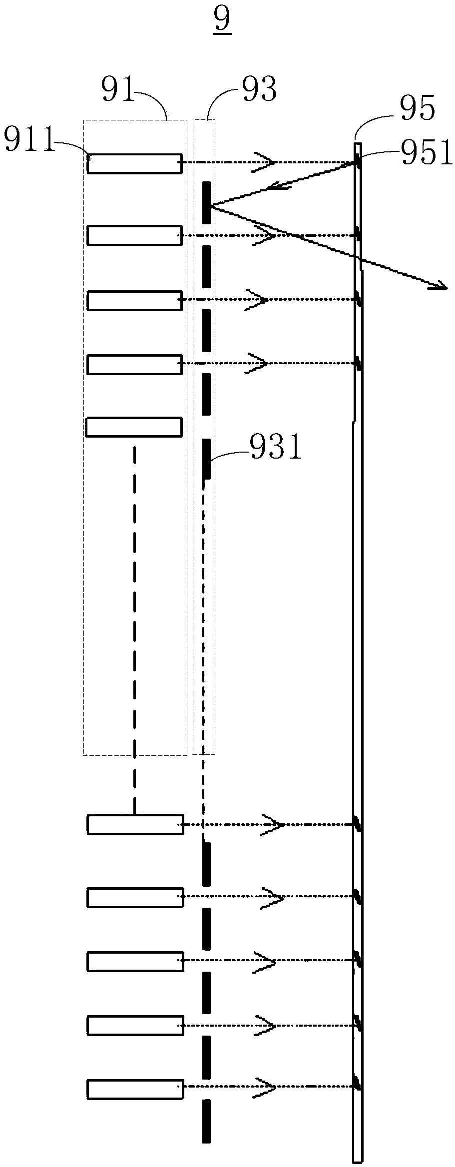
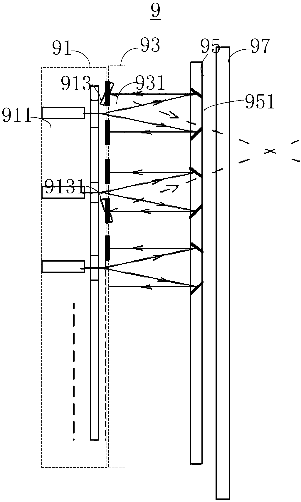
technical field [0001] The invention relates to the technical field of three-dimensional display and measurement, in particular to a calibration method and device. Background technique [0002] The projection display device generally includes a light source array module, a micro-vibration mirror array, and a light reflection plate. The micro-vibration mirror array includes a plurality of micro-vibration mirror units, and the light reflection plate includes a plurality of micro-reflection units. The micro-reflection units on the light reflection plate are in one-to-one correspondence, and the light emitted by the light source array module is coupled into the micro-vibration mirror array through the light reflection plate, and the micro-vibration mirror array is controlled to project micro-vibration mirrors to multiple virtual object points in space. beams so that multiple beamlets projected onto each virtual object point form a launch beam. When the user receives the beam co...

Claims


Application Information

Patent Timeline
IPC IPC(8): G06T7/80G06F17/16
CPCG06F17/16G06T7/80
Inventor 黄琴华李文权
Owner SHENZHEN SKYWORTH NEW WORLD TECH CO LTD
Why Eureka
Try Eureka