A tunnel imaging robot and underground surveying and mapping control method
What is AI technical title?
AI technical title is built by Patsnap AI team. It summarizes the technical point description of the patent document.
A control method and robot technology, applied in the field of surveying and mapping, can solve problems such as inaccurate data and achieve clear images
Active Publication Date: 2020-12-08
青岛振华信息工程有限公司
View PDF2 Cites 0 Cited by
Summary
Abstract
Description
Claims
Application Information
AI Technical Summary
This helps you quickly interpret patents by identifying the three key elements:
Problems solved by technology
Method used
Benefits of technology
Problems solved by technology
[0003] The purpose of the present invention is to overcome the deficiencies of the prior art, to provide a tunnel imaging robot and underground surveying and mapping control method, which solves the problem of inaccurate traditional tunnel surveying and mapping data. Accurate image acquisition at different levels, etc. If encountering a deep hole environment, the imaging robot can be recovered quickly through the recovery device. The structure is simple and easy to use.
Method used
Image
Click on the blue label to locate the original text in one second.
Reading with bidirectional positioning of images and text.
Examples
Embodiment 1
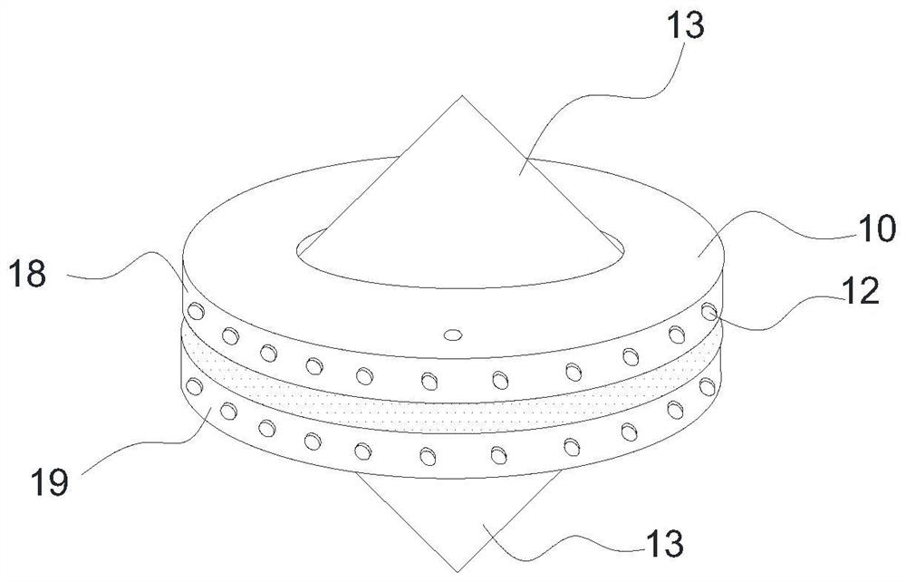
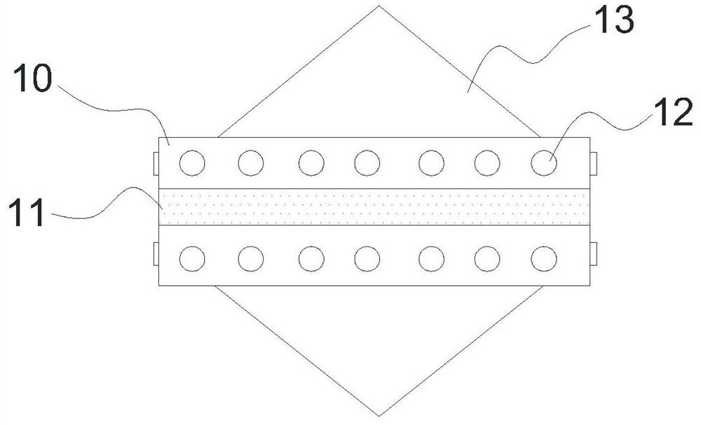
[0033] This embodiment provides a tunnel imaging robot, please refer to the attached figure 1 - attached Figure 4 As shown, it includes an imaging robot body 10 and a recovery device 17, and the imaging robot body 10 includes a casing, a traveling device and a surveying and mapping imaging device;
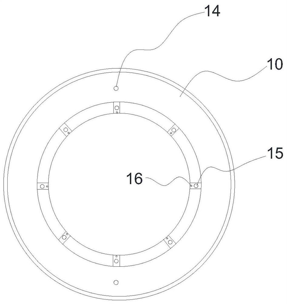
[0034] The shell is a circular structure, and the shell includes an upper shell 18 and a lower shell 19, the upper shell 18 and the lower shell 19 are fixed by a screw structure, and the center of the upper shell 18 and the lower shell 19 is provided with a concave A circular groove, a plurality of mutually symmetrical camera gaps are arranged in the circular groove, a camera 15 and an LED light 16 are respectively installed in each camera gap, and a cone structure 13 is also arranged in the circular groove;
[0035] The traveling device is used to provide the traveling power of the imaging robot body 10, and change the traveling direction and position by adjusting the length of ...
Embodiment 2
[0042] In this embodiment, on the basis of Embodiment 1, the imaging robot body 10 is provided with an ultrasonic generating device 14 , and the recovery device 17 is provided with an ultrasonic receiving device.
[0043] When the imaging robot 10 enters a deep cave environment, it is very difficult to recover and measure distances. The imaging robot 10 described in this embodiment can send ultrasonic waves to the recovery device 17 in a deep cave environment, and the recovery device 17 receives the ultrasonic waves, and calculates the distance between the imaging robot 10 and the recovery device 17 by calculating the receiving time of the ultrasonic waves.
Embodiment 3
[0045] In this embodiment, on the basis of Embodiment 1 and Embodiment 2, the traveling support feet 12 are cylindrical telescopic columns, and each traveling supporting foot 12 corresponds to a position feature code.
[0046] By setting each traveling support foot 12 to include a unique position characteristic code, a relationship link table between each traveling support foot 12 and the position characteristic code is established, and each traveling support of forward drive, reverse drive and resident detection is preset according to the relation link table The telescopic state and telescopic order of pin 12.
PUM
Abstract
The invention discloses a tunnel imaging robot and a ground mapping control method. The tunnel imaging robot comprises an imaging robot body and a retracting device. The imaging robot body comprises ahousing, a traveling device, and a mapping imaging device. The housing comprises an upper housing and a lower housing which are fixed by a thread structure. The center of the upper housing and the lower housing is provided with a concave circular groove that is provided with a plurality of mutually symmetrical imaging gaps. Each camera gap is provided with a camera and an LED light. A conical body structure is also disposed in the circular groove. The traveling device is used for providing the traveling power of the imaging robot body and changing the traveling direction and position by adjusting the length of a traveling support foot. According to the tunnel imaging robot and the ground mapping control method, the problem of inaccurate data in traditional tunnel mapping is solved. The tunnel imaging robot performs accurate image acquisition on rock layers and fault planes inside the tunnel. The retracting device quickly retracts the imaging robot from the deep hole environment. Therefore, the invention has a simple structure and is convenient to use.
Description
technical field [0001] The invention relates to the technical field of surveying and mapping, in particular to a tunnel imaging robot and a control method for underground surveying and mapping. Background technique [0002] During tunnel construction, the geological conditions exposed by excavation must be surveyed and mapped. The first item that must be tested in the measurement and monitoring projects of railway tunnels, highway tunnels, and water conservancy and hydropower water transmission tunnels is the geological sketch of the face. During the construction of the tunnel, it is also necessary to conduct geological survey and mapping of the surrounding rock mass after each blasting or excavation cycle in a timely manner, and draw the longitudinal section of the tunnel and submit it in the completion documents. When making tunnel face sketches and geological surveying of tunnel side walls and arches, it is necessary to measure the occurrence of rock formations (includin...
Claims
Application Information
Patent Timeline
Application Date:The date an application was filed.
Publication Date:The date a patent or application was officially published.
First Publication Date:The earliest publication date of a patent with the same application number.
Issue Date:Publication date of the patent grant document.
PCT Entry Date:The Entry date of PCT National Phase.
Estimated Expiry Date:The statutory expiry date of a patent right according to the Patent Law, and it is the longest term of protection that the patent right can achieve without the termination of the patent right due to other reasons(Term extension factor has been taken into account ).
Invalid Date:Actual expiry date is based on effective date or publication date of legal transaction data of invalid patent.

