Method and system for robot navigation based on virtual wall for projection
A navigation method and robot technology, applied in the field of robot navigation method and system based on projected virtual wall, to achieve the effect of wide recognition coverage, multi-expansion, and simplified operation
- Summary
- Abstract
- Description
- Claims
- Application Information
AI Technical Summary
Problems solved by technology
Method used
Image
Examples
Embodiment 1
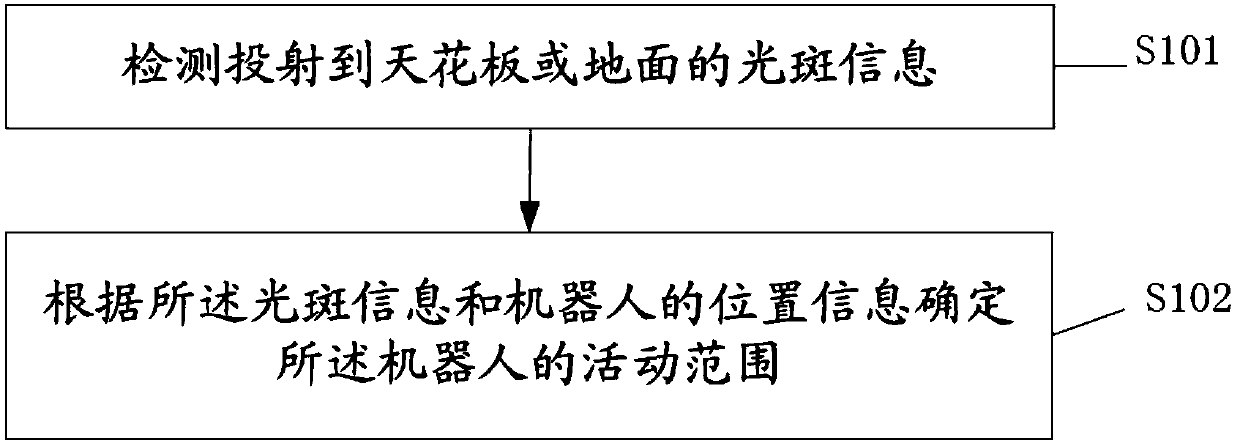
[0055] This embodiment combines figure 1 A method for robot navigation based on projected virtual walls is illustrated, including:
[0056] S101. Detect light spot information projected to the ceiling or the ground;
[0057]S102. Determine an activity range of the robot according to the light spot information and the position information of the robot.
[0058] Wherein, the light spot information includes: the number of light spots, the geometric shape of the light spots, and the position information of the light spots.
[0059] After determining the scope of the robot's activities, it also includes:
[0060] The robot performs preset operations within the activity range.
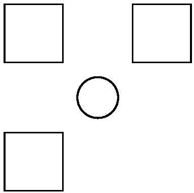
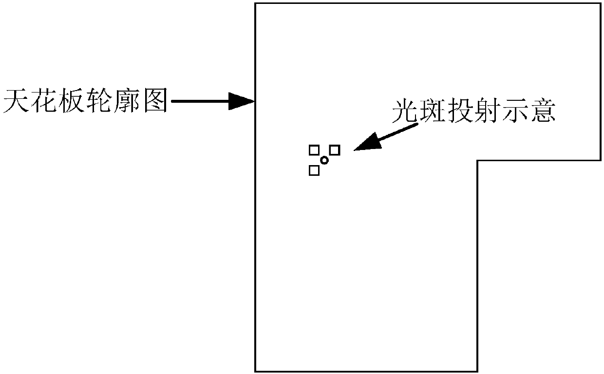
[0061] The embodiments of the present invention generate the required light spots for robot visual navigation through the light spot emission device; and project the light spots to the ceiling, preferably, such as figure 2 As shown, the spot emitting device of the embodiment of the present invention can...
Embodiment 2
[0066] This embodiment takes the sweeping robot as an example to illustrate the robot navigation method based on the projected virtual wall in the embodiment of the present invention. During the operation of the sweeping robot, the top camera continuously captures ceiling information, detects whether there is light spot information in the ceiling, and continuously Added to the control task. Since the area captured by the camera is limited, and there may be other light spot information during the movement, the strategy of this virtual wall is local and constantly updated. According to the number of light spots and the relative position information between the geometric shape of the light spots and the sweeping robot, different virtual wall functions can be defined.
[0067] According to the above relative positional relationship, the preset functions of the sweeping robot under various numbers of spots and positions of spots can be preset.
[0068] Determining the activity ran...
Embodiment 3
[0082] The difference between this embodiment and Embodiment 2 is that the number of light spots in this embodiment is 2.
[0083] Determining the activity range of the robot according to the light spot information and the position information of the robot includes:
[0084] When the number of the light spots is 2, the geometric shape is a straight line obtained through the centers of the two light spots; the range of activity of the robot is determined to be one of the areas on both sides formed by the projection of the straight line on the ground .
[0085] When the light spot is projected to the ceiling, the projection area of the geometric shape of the two light spots on the ground is the area where the geometric shape of the light spot on the ceiling is vertically projected on the ground. When the light spot is projected on the ground, the two light spots The projection area of the geometric shape formed on the ground is the area formed by the spot itself on the grou...
PUM
 Abstract
Description
Claims
Application Information
 - R&D
- Intellectual Property
- Life Sciences
- Materials
- Tech Scout
- Unparalleled Data Quality
- Higher Quality Content
- 60% Fewer Hallucinations
Browse by: Latest US Patents, China's latest patents, Technical Efficacy Thesaurus, Application Domain, Technology Topic, Popular Technical Reports.
© 2025 PatSnap. All rights reserved.Legal|Privacy policy|Modern Slavery Act Transparency Statement|Sitemap|About US| Contact US: help@patsnap.com


