Communication system for cascaded power conversion equipment

A communication system and power conversion technology, applied in the field of communication systems, can solve problems such as increased production costs, difficult line management, and a large number of optical fibers, and achieve the effects of simplified wiring, easy modularization, and high reliability

Inactive Publication Date: 2019-04-02
DELTA ELECTRONICS (SHANGHAI) CO LTD
View PDF10 Cites 3 Cited by
  • Summary
  • Abstract
  • Description
  • Claims
  • Application Information

AI Technical Summary

Problems solved by technology

In order to achieve reliable communication and high-voltage isolation between each power module 1a and the main control system 1b, a pair of independent optical fibers is installed between each power module 1a and the main control system 1b, resulting in a large number of optical fibers and difficult cable management, thereby increasing production cost

Method used


Image

  • Communication system for cascaded power conversion equipment
  • Communication system for cascaded power conversion equipment
  • Communication system for cascaded power conversion equipment

Examples


Embodiment Construction

[0046] The present invention is described in further detail below in conjunction with accompanying drawing and specific embodiment: present embodiment is carried out under the premise of technical solution of the present invention, has provided embodiment and operation process, but protection scope of the present invention is not limited to following Example.

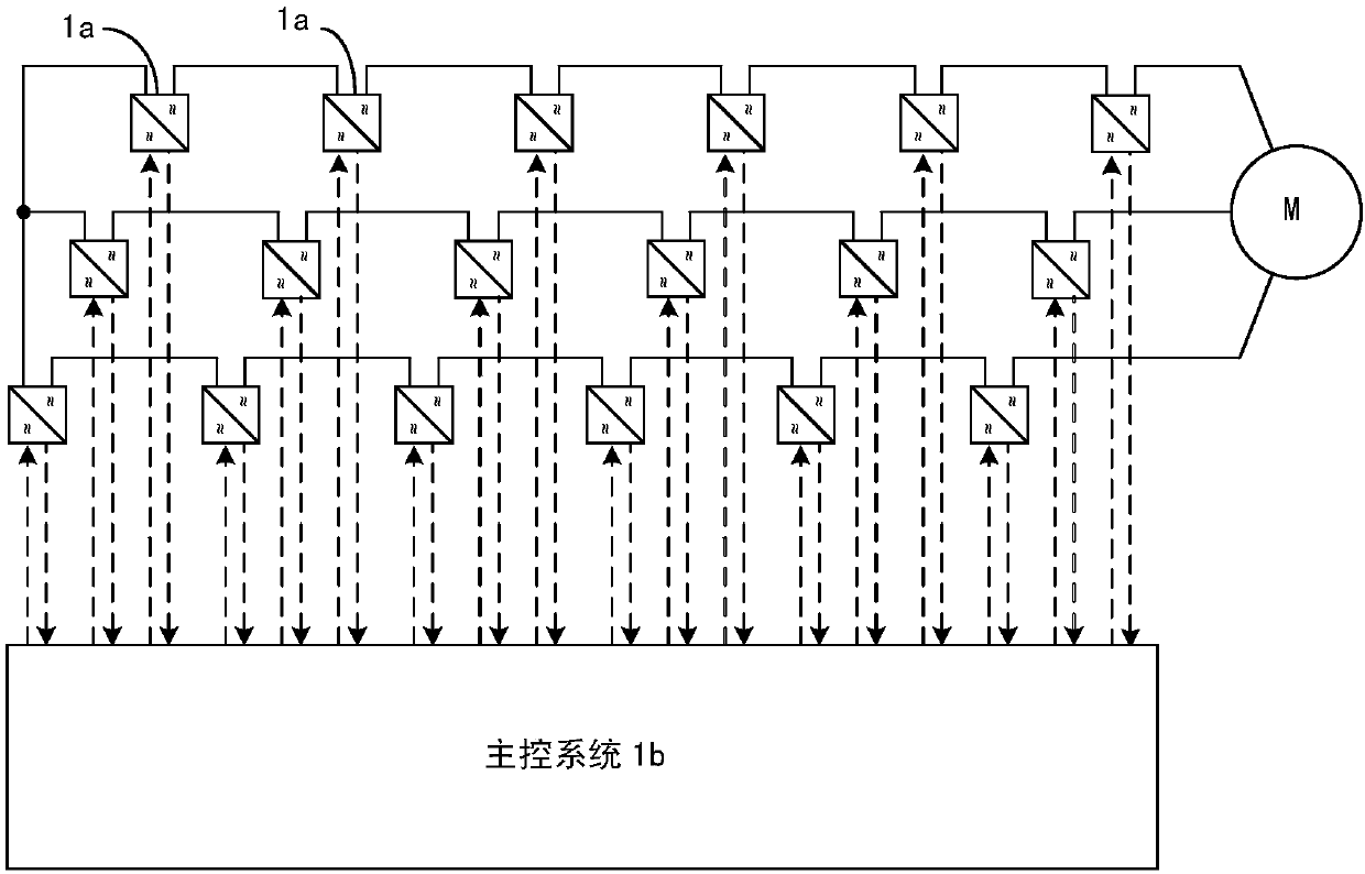
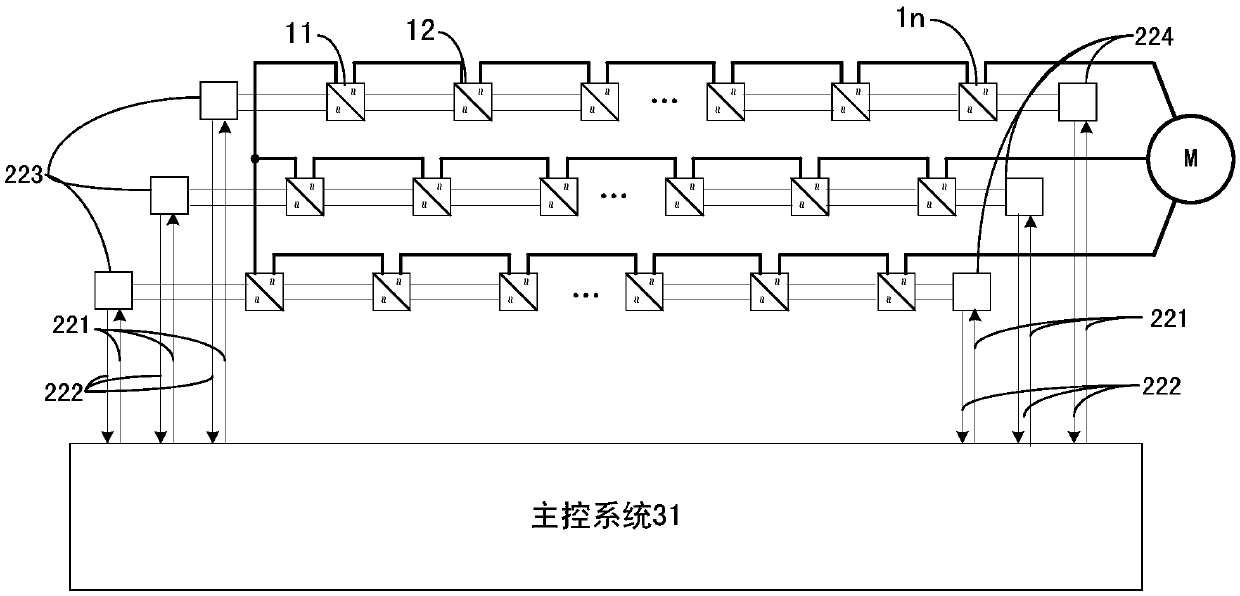
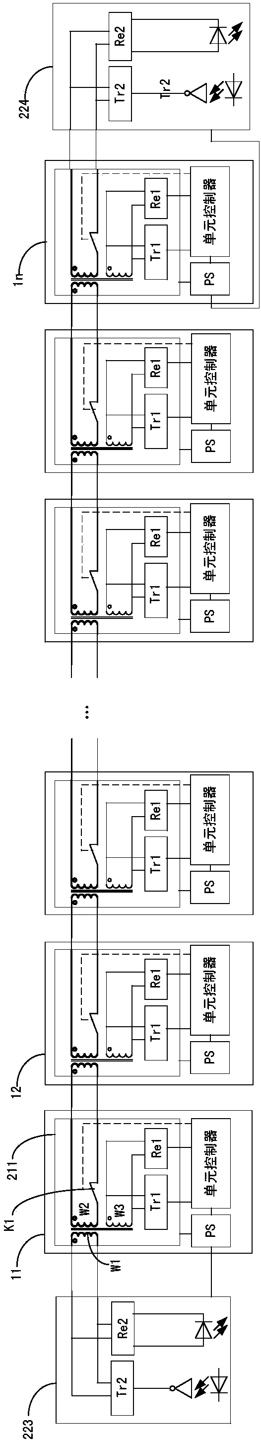
[0047] Please refer to Figure 2-4 , figure 2 It is a schematic diagram of the overall connection of the cascaded power conversion equipment of the present invention; image 3 It is a structural schematic diagram of the communication system of the present invention; Figure 4 It is a schematic diagram of the first embodiment of the low-voltage communication unit of the present invention. like Figure 2-4 As shown, each phase of cascaded power conversion equipment includes a plurality of power modules 11...1n connected in series and a communication system, where n is a positive integer; the communication unit of eac...


PUM


Abstract

The invention discloses a communication system for cascaded power conversion equipment and cascaded power conversion equipment. Each phase of the cascaded power conversion equipment comprises multiplepower modules connected in series and a communication system; each communication system comprises multiple low-voltage communication units and multiple optical fibers; the multiple low-voltage communication units are arranged in the multiple power modules in a one-to-one correspondence mode; the multiple low-voltage communication units are connected in series; and the multiple optical fibers areconnected between the low-voltage communication units and the main control system of the cascaded power conversion equipment.

Description

technical field [0001] The present invention relates to a communication system for cascaded power conversion equipment, in particular to a communication system capable of reducing the number of optical fibers and transceivers of cascaded power conversion equipment. Background technique [0002] Please refer to figure 1 , figure 1 It is a structural schematic diagram of an existing communication system for cascaded power conversion equipment. like figure 1 As shown, each phase of the cascaded power conversion equipment in the prior art is formed by connecting multiple power modules 1a in series, and there are many power modules 1a in the cascaded power conversion equipment (for example, for a common 6KV system, each phase of the power module 1a connected in series The number of 1a is about 5 to 6, and the number of power modules of the three-phase cascaded power conversion equipment is as high as 15 to 18), each power module 1a needs to be connected with the main control s...

Claims


Application Information

Patent Timeline
Patent Type & Authority Applications(China)
IPC IPC(8): H04B10/25
CPCH04B10/2589H04B10/25891H02M7/49H02P27/14H04B10/275H04B10/801H02P27/04H02M11/00
Inventor 王凯周代平郎永强赵文江
Owner DELTA ELECTRONICS (SHANGHAI) CO LTD
Why Eureka
Try Eureka