

Fluid apparatus and nozzle
A fluid and flow path technology, applied in the field of nozzles for jetting fluids, can solve the problems of design changes, inability to install a filter part on the main body, etc., and achieve the effect of preventing the fluid being no longer jetted
- Summary
- Abstract
- Description
- Claims
- Application Information
AI Technical Summary
Problems solved by technology
Method used
Image

Examples
Embodiment approach 1
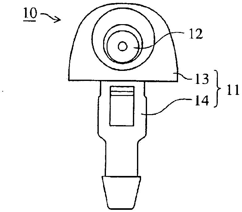
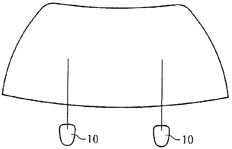
[0062] Figure 10-12 illustrated in the figure 1 A fluid device 12 (also referred to as a nozzle section) used in a nozzle 10 such as a washer nozzle is shown.
[0063] The fluid device 12 has a supply surface 21 , an injection surface 23 , an upstream path 26 , a downstream path 27 , and a partition wall 29 .
[0064] The supply surface 21 is located on the upstream side and has a supply port 22 . The supply port 22 receives supply of fluid. The supply port 22 is divided into five areas by the partition wall 29 . One of them is the central area, and the other four are peripheral areas. The central area is connected to all surrounding areas. Each peripheral area is wider than the central area.
[0065] The injection surface 23 is located on the downstream side and has an injection port 24 . The ejection port 24 ejects fluid to the outside.
[0066] The downstream passage 27 (also referred to as a flow passage for injection or a main flow passage) is a hole having a sub...
Embodiment approach 2
[0079] Figures 13 to 15 illustrated in the figure 1 The fluidic device 12 used in the illustrated nozzle 10 and the like.
[0080] The fluid device 12 is the same as that of Embodiment 1, but differs in the following points.
[0081] The fluid device 12 is formed by fitting the inner part 31 into the outer part 36 .
[0082] The outer part 36 (also referred to as an exterior part) has the injection surface 23 , the storage space 37 and the flow path 38 .
[0083] The injection surface 23 has injection ports 24 .
[0084] The accommodation space 37 accommodates the inner part 31 .
[0085] The flow path 38 communicates with the storage space 37 and the injection port 24 .
[0086] The inner part 31 (also referred to as a flow path part) has a supply surface 21 , a peripheral wall 32 , a bottom wall 33 , an upstream path 26 , a flow path 34 , and a partition wall 29 .
[0087] The supply surface 21 has a supply port 22 .
[0088] The flow paths 34 and 38 form the downstr...
Embodiment approach 3
[0092] Figures 16-17 illustrated in the figure 1 The fluidic device 12 used in the illustrated nozzle 10 and the like.
[0093] The fluid device 12 is the same as that of Embodiment 1, but differs in the following points.
[0094] The partition walls 29 intersect at the center on the upstream side.
[0095] The supply port 22 is divided into four peripheral areas by a partition wall 29 . There is no central area.
[0096] The downstream path 27 does not communicate with the supply port 22 .
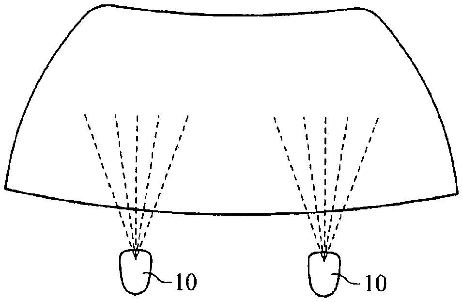
[0097] Fluid is supplied to the supply port 22 , and all the fluid enters the upstream path 26 from the peripheral area, enters the downstream path 27 through the connection port 28 , and is sprayed from the injection port 24 toward the outside.
[0098] Since the partition wall 29 is connected at the center on the upstream side, it is possible to prevent the partition wall 29 from being deformed by the pressure of the fluid and changing the width of the connection port 28 .
PUM
 Abstract
Description
Claims
Application Information