
Floating block structure and mold

A floating block and mold technology, applied in forming tools, manufacturing tools, metal processing equipment, etc., can solve the problems of loose block 30', hurting people, mold damage, etc.

Inactive Publication Date: 2019-04-05
QINGDAO HISENSE MOLD
View PDF6 Cites 1 Cited by
  • Summary
  • Abstract
  • Description
  • Claims
  • Application Information

AI Technical Summary

Problems solved by technology

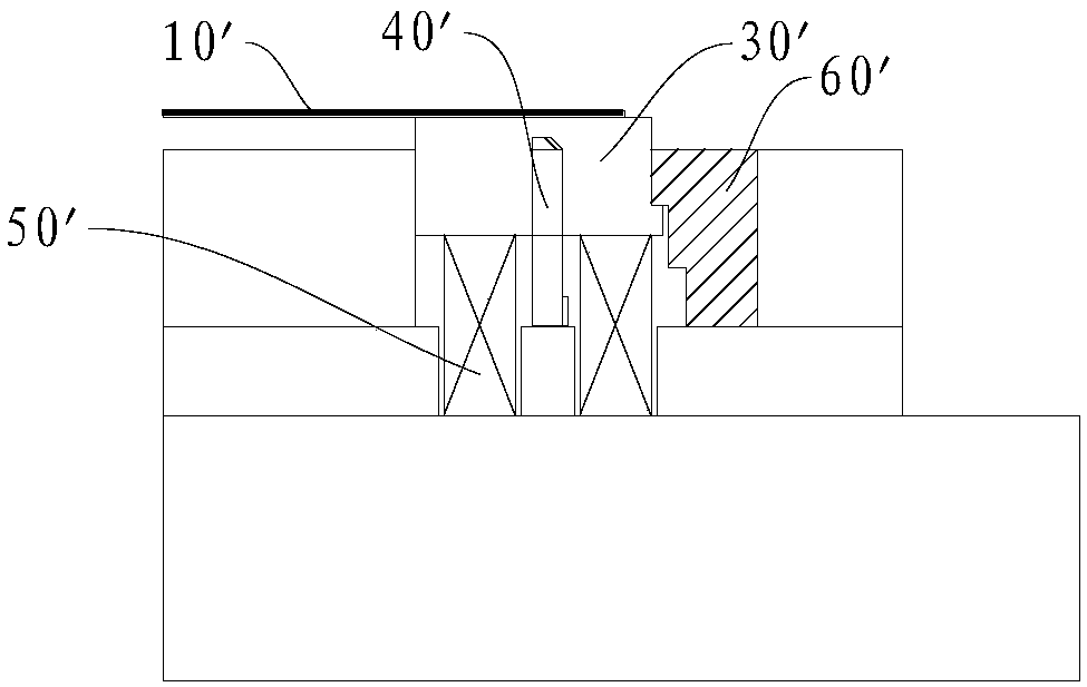
like image 3 As shown, there is another solution is to use the floating block 30' containing the molding insert 40', but due to the influence of the spring 50' being relatively large, it is easy to cause the pressing block 60' to pop out under force and the floating block 30' to loosen. This will lead to safety accidents such as mold damage, product damage, and even injury

Method used


Image

  • Floating block structure and mold
  • Floating block structure and mold
  • Floating block structure and mold

Examples


Embodiment Construction

[0031] The specific embodiments of the present invention will be described in detail below in conjunction with the accompanying drawings, but the present invention can be implemented in many different ways defined and covered by the claims.

[0032] refer to Figure 4-Figure 6 , the floating block structure in one embodiment of the present invention is set on the lower mold 100 of the mold for stripping. The floating block structure includes a floating block 200 , a pressing block 300 and an ejector pin assembly 400 . The floating block 200 is movably arranged on the lower mold 100, and the floating block 200 has a floating block stopper 210, which cooperates with the floating block stopper fitting part 310 on the pressing block 300 to limit the upward displacement of the floating block 200 and prevent the floating block from 200 is deviated from lower mold 100. The ejector pin assembly 400 includes an ejector pin 410 and an elastic member 420 , the ejector pin 410 is dispos...


PUM


Abstract

The invention discloses a floating block structure and a mold. The floating block structure comprises a floating block, pressing blocks and lifting pin assemblies; the floating block is movably arranged on a lower mold and provided with floating block limiting parts, the floating block limiting parts are matched with floating block limiting matching parts on the pressing blocks, and upward displacement of the floating block is restricted; the lifting pin assemblies comprise lifting pins and elastic pieces, the lifting pins are arranged on the lower part of the floating block, and the lifting pins are connected with the elastic pieces and can move up and down to drive the floating block to move up and down; the lifting pins are provided with lifting pin limiting parts, the lifting pin limiting parts are matched with lifting pin limiting matching parts on the lower mold, upward displacement of the lifting pins is restricted; and when the floating block moves upward to the withdrawing position, the lifting pin limiting parts abut against the lifting pin limiting matching parts. According to the floating block structure, the floating block is combined with the lifting pins, the strokemargins of the floating block are reserved, the floating block in the final state is not subjected to stress, the condition that pressing blocks cannot be subjected to stress and pop up can be ensured, and the mold and products are protected; meanwhile, limiting is carried out through the lifting pins, the withdrawing height can be adjusted by replacing the lifting pins; and the parts adopt mold inserting structures, the parts are convenient to assemble, disassemble and adjust.

Description

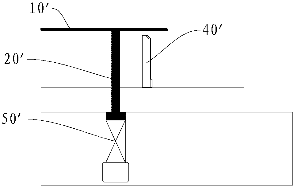
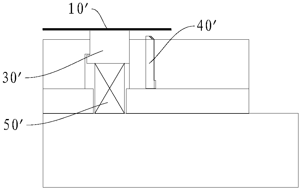
technical field [0001] The invention relates to the technical field of moulds, in particular to a floating block structure and a mould. Background technique [0002] For some molds that are formed upwards but have no lower strips, it is necessary to design the floating block stripping locally. In existing molds, such as figure 1 As shown, one solution is to use the ejector pin 20'. In this method, there is a certain distance between the ejector pin 20' and the molding insert 40'. Due to the different directions of the upper and lower forces and the small force area, the material 10' out of shape. Such as figure 2 As shown, another kind of scheme is to adopt independent floating block 30 ', and this method is similar to the ejector pin method. Such as image 3 As shown, there is another solution is to use the floating block 30' containing the molding insert 40', but due to the influence of the spring 50' being relatively large, it is easy to cause the pressing block 60'...

Claims


Application Information

Patent Timeline
Patent Type & Authority Applications(China)
IPC IPC(8): B21D37/10B21D55/00
CPCB21D37/10B21D55/00
Inventor 陈东冷云修立伟徐佳驹刘昊龙
Owner QINGDAO HISENSE MOLD
Learn More