Steel bar cutter for well lid installing

A technology for cutting and installing steel bars, which is applied in the field of steel bar cutters for manhole cover installation. It can solve the problems of low cutting efficiency of steel bars and easy sore arms, and achieve the effect of improving cutting efficiency, preventing arm soreness, and convenient cutting

Active Publication Date: 2019-04-05
林向亮
View PDF6 Cites 4 Cited by
  • Summary
  • Abstract
  • Description
  • Claims
  • Application Information

AI Technical Summary

Problems solved by technology

[0003] In order to overcome the shortcoming that people use hand-held steel bar pliers to cut off steel bars, people's arms are prone to soreness and the efficiency of cutting off steel bars is low. The technical problem of the present invention is to provide a steel bar for well cover installation that can prevent sore arms and improve cutting efficiency truncate

Method used


Image

  • Steel bar cutter for well lid installing
  • Steel bar cutter for well lid installing
  • Steel bar cutter for well lid installing

Examples


Embodiment 1

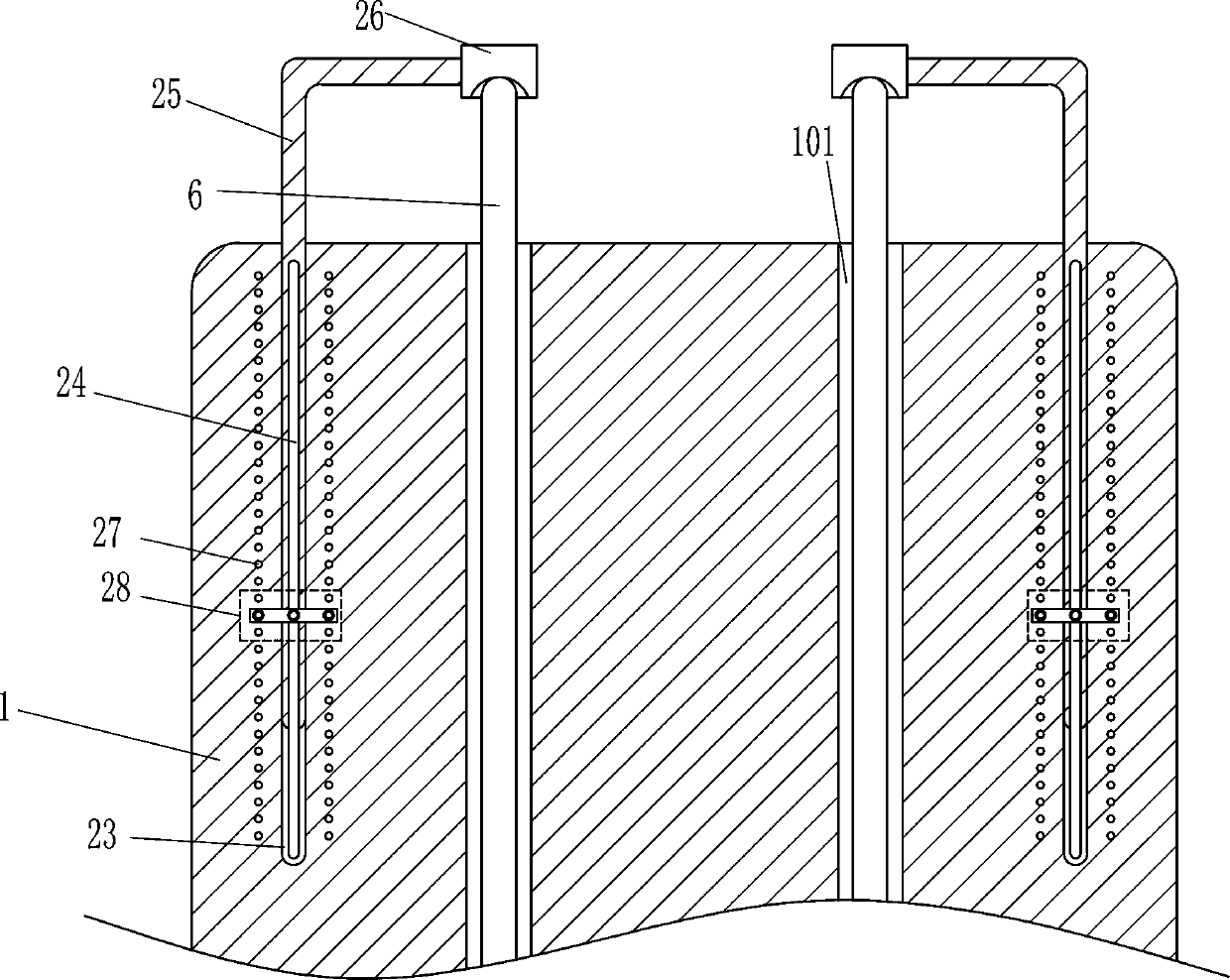
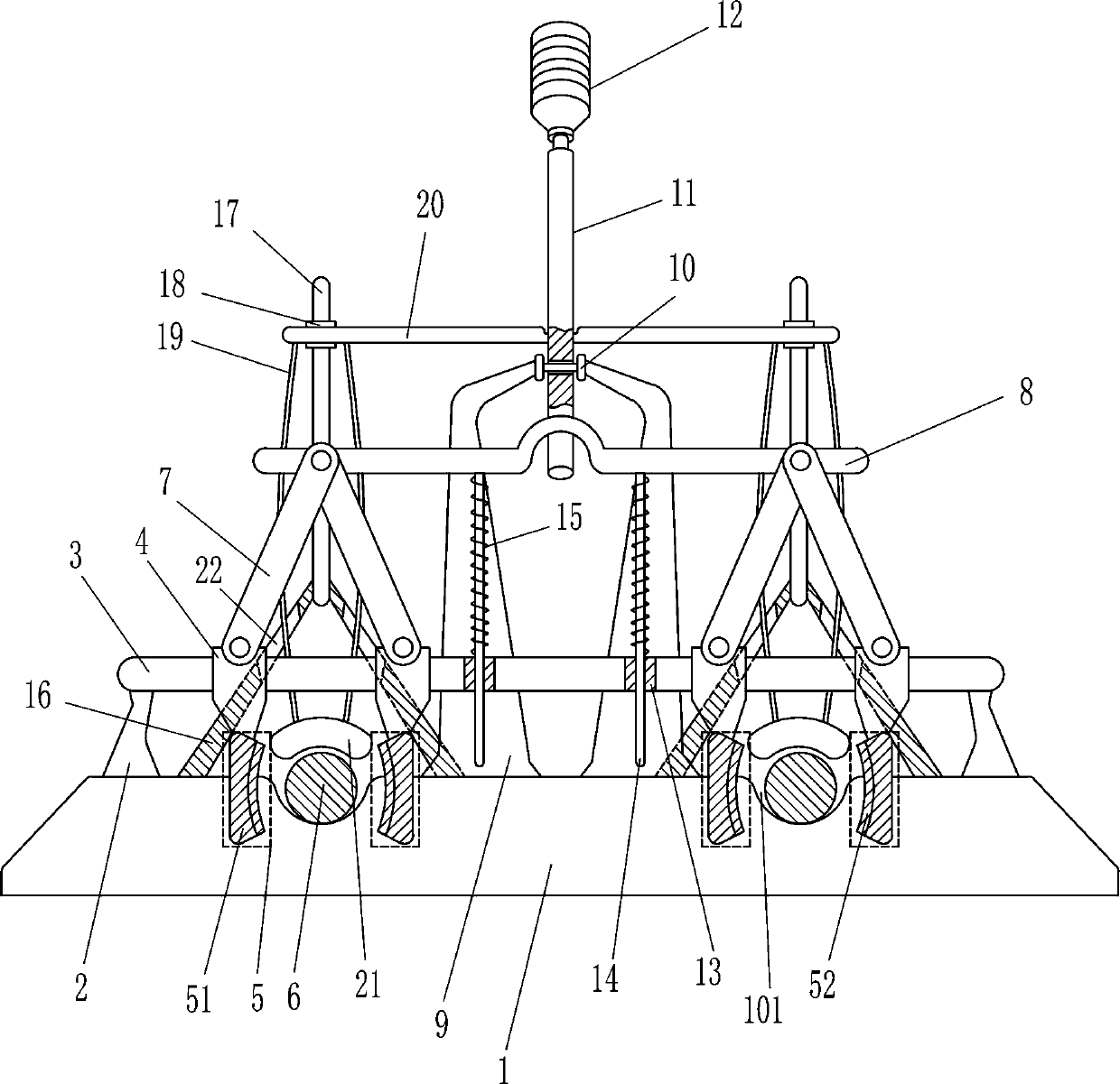
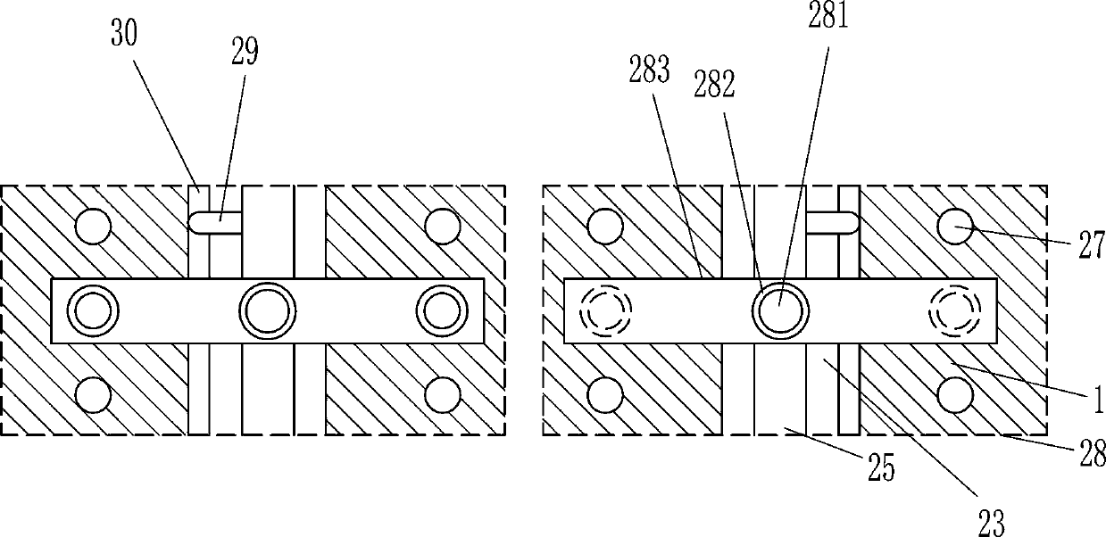
[0016] A steel bar cutter for well cover installation, such as figure 1 As shown, it includes a bottom plate 1, a pole 2, a guide rail 3, a guide block 4, a cutting device 5, a steel bar body 6, a connecting rod 7, a concave rod 8, a connecting plate 9, a rotary joint 10, a telescopic rod 11, and a handle 12. Guide sleeve 13, guide rod 14 and spring 15, the left and right sides of the top of the bottom plate 1 are provided with placement grooves 101 for placing the steel bar body 6, the left and right sides of the top of the bottom plate 1 are fixed with poles 2, and the bottom plate 1 passes through The way of bolt connection is connected with the support rod 2, and the guide rail 3 is arranged between the top ends of the left and right two support rods 2, and the support rod 2 is connected with the guide rail 3 by welding, and there are four guide blocks 4, all of which are sliding On the guide rail 3, the bottom of the guide block 4 is equipped with a cutting device 5 that ...

Embodiment 2

[0018] A steel bar cutter for well cover installation, such as figure 1 As shown, it includes a bottom plate 1, a pole 2, a guide rail 3, a guide block 4, a cutting device 5, a steel bar body 6, a connecting rod 7, a concave rod 8, a connecting plate 9, a rotary joint 10, a telescopic rod 11, and a handle 12. Guide sleeve 13, guide rod 14 and spring 15, the left and right sides of the bottom plate 1 top are all provided with placement grooves 101 for placing the steel bar body 6, the left and right sides of the bottom plate 1 top are all fixed with support rods 2, two left and right A guide rail 3 is arranged between the tops of the struts 2, and four guide blocks 4 are arranged on the guide rails 3, and the bottom of the guide block 4 is equipped with a cutting device 5 that can cut off the steel bar body 6, and the guide block 4 A connecting rod 7 is hinged on the top of the top of the left and right sides, and a concave rod 8 is hingedly connected between the tops of the tw...

Embodiment 3

[0021] A steel bar cutter for well cover installation, such as figure 1 As shown, it includes a bottom plate 1, a pole 2, a guide rail 3, a guide block 4, a cutting device 5, a steel bar body 6, a connecting rod 7, a concave rod 8, a connecting plate 9, a rotary joint 10, a telescopic rod 11, and a handle 12. Guide sleeve 13, guide rod 14 and spring 15, the left and right sides of the bottom plate 1 top are all provided with placement grooves 101 for placing the steel bar body 6, the left and right sides of the bottom plate 1 top are all fixed with support rods 2, two left and right A guide rail 3 is arranged between the tops of the struts 2, and four guide blocks 4 are arranged on the guide rails 3, and the bottom of the guide block 4 is equipped with a cutting device 5 that can cut off the steel bar body 6, and the guide block 4 A connecting rod 7 is hinged on the top of the top of the left and right sides, and a concave rod 8 is hingedly connected between the tops of the tw...


PUM


Abstract

The invention relates to a steel bar cutter, in particular to a steel bar cutter for well lid installing. The technical propose that the steel bar cutter for well lid installing can prevent arm achingand improve the cutting efficiency is achieved. According to the technical scheme, the steel bar cutter for well lid installing comprises a bottom plate, supporting rods, a guiding rail, guiding blocks, cutting devices, steel bar bodies, connecting rods, a concave rod, a connecting plate, a rotating joint, a telescopic rod, a holding handle, guiding sleeves and the like; and the left side and theright side of the top of the bottom plate are each provided with a containing groove used for containing the corresponding steel bar body, the supporting rods are fixed to the left side and the rightside of the top of the bottom plate, the guiding rail is arranged between the top ends of the left supporting rod and the right supporting rod, and the four guiding blocks are arranged. According tothe steel bar cutter for well lid installing, the steel bar bodies can be cut in the mode that the cutting devices on the left side and the right side are close to each other, therefore, a user does not need to hold steel bar pliers to cut the steel bar bodies, arm aching can be prevented, and the cutting efficiency can be improved.

Description

technical field [0001] The invention relates to a steel bar cutter, in particular to a steel bar cutter for well cover installation. Background technique [0002] When making sewer manhole covers, people will first use steel bars to make the frame of the sewer manhole cover, and then pour cement into it to complete the production of the sewer manhole cover. Cut off, so people's arms are prone to soreness, and the cutting efficiency of steel bars is low. In order to improve the cutting efficiency of steel bars, people will rely on experience to cut off steel bars, which will lead to greater deviation in cut length and poor cut quality. Contents of the invention [0003] In order to overcome the shortcoming that people use hand-held steel bar pliers to cut off steel bars, people's arms are prone to soreness and the efficiency of cutting off steel bars is low. truncater. [0004] The technical solution of the present invention is: a steel bar cutter for well cover installat...

Claims


Application Information

Patent Timeline
IPC IPC(8): B21F11/00
CPCB21F11/00
Inventor 肖龙
Owner 林向亮
Why Eureka
Try Eureka