Axle hole processing clamp and method for dual-fluted-disc-driven knotter bracket

A knotter and hole processing technology, which is applied in the direction of manufacturing tools, metal processing equipment, metal processing machinery parts, etc., to achieve the effect of eliminating repeated alignment, convenient and simple loading and unloading of workpieces, and saving processing time

Pending Publication Date: 2019-04-05
泰州市力鼎机械设备有限公司
View PDF1 Cites 0 Cited by
  • Summary
  • Abstract
  • Description
  • Claims
  • Application Information

AI Technical Summary

Problems solved by technology

[0003] Aiming at the existing problems, the present invention provides a method for processing the shaft hole of the knotter bracket driven by double toothed disks and a fixture. All the structural elements to be processed of the knotter bracket can be processed by clamping the knotter bracket at one time, effectively saving knots The processing time of the knotter bracket is reduced, the processing cost is reduced, the yield of the knotter bracket is significantly improved, and the problem of batch processing of the knotter bracket is solved

Method used


Image

  • Axle hole processing clamp and method for dual-fluted-disc-driven knotter bracket
  • Axle hole processing clamp and method for dual-fluted-disc-driven knotter bracket
  • Axle hole processing clamp and method for dual-fluted-disc-driven knotter bracket

Examples


Embodiment 1

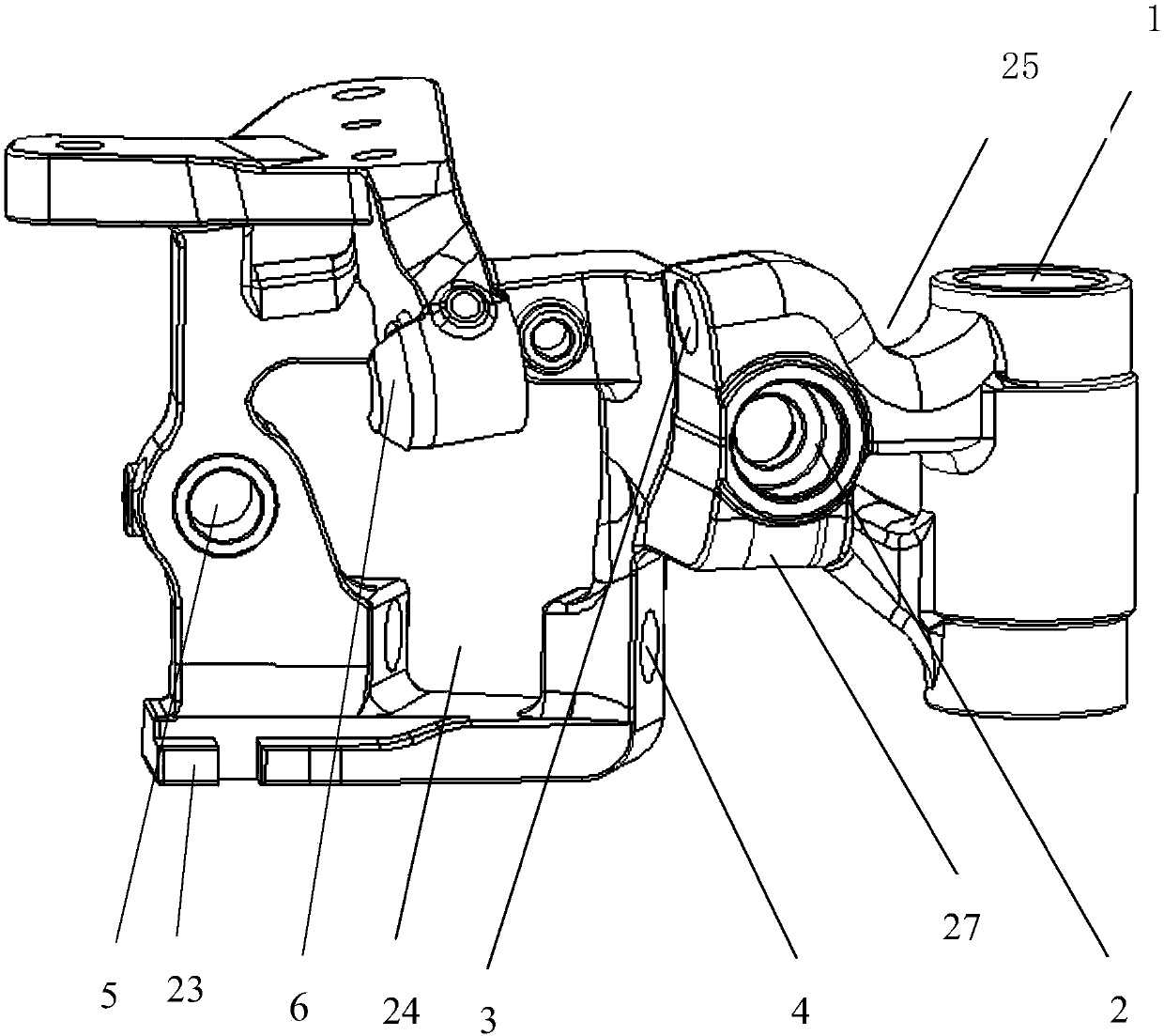
[0046] figure 1 Shown is the bracket of the double tooth disc drive knotter according to the present invention, including a main shaft hole 1, a knife arm shaft hole 2, a knotting nozzle shaft hole 3, a worm shaft hole 4, a rope clamp disc shaft hole 5 and a knotting nozzle shaft Hole cam surface6.

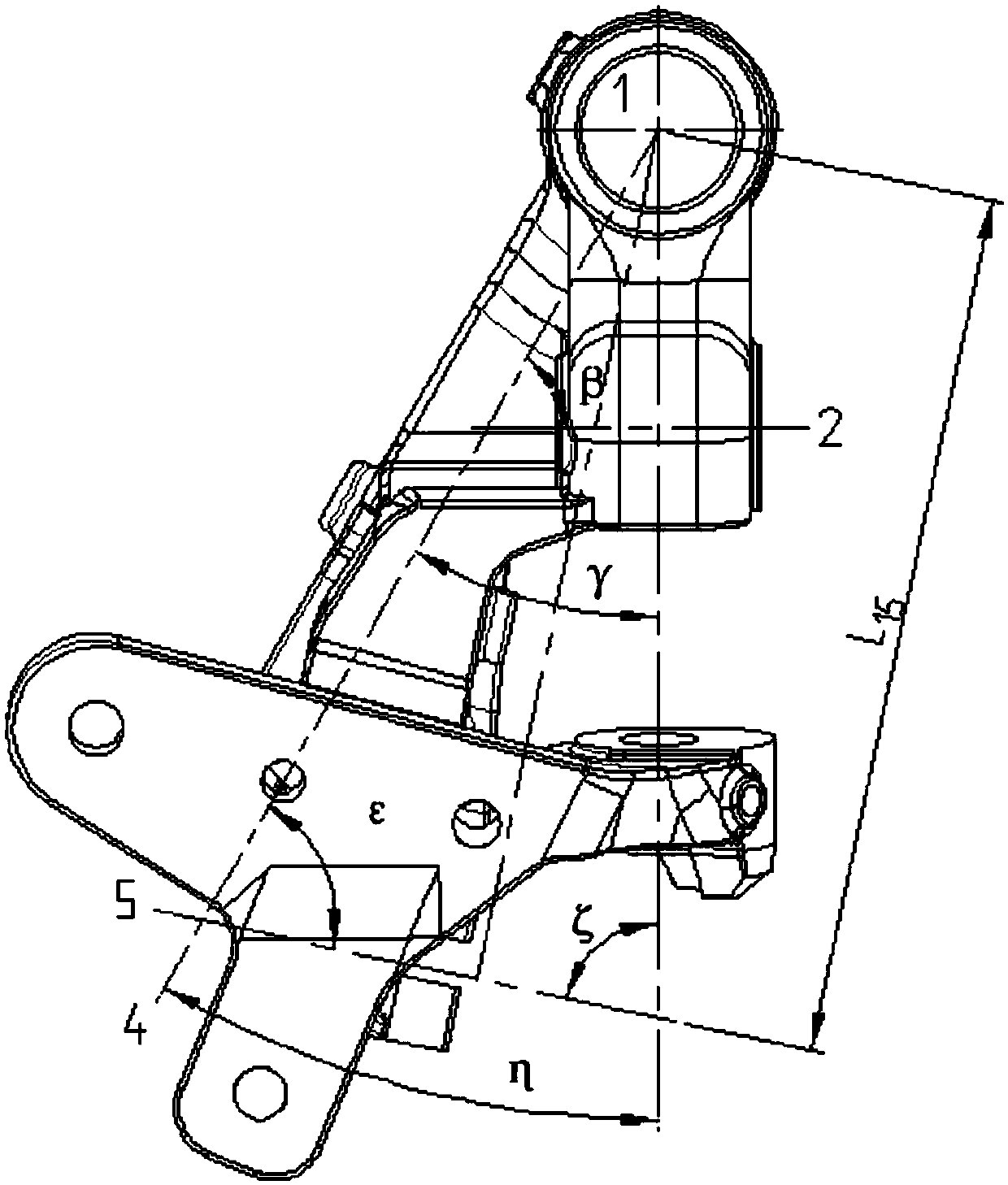
[0047] figure 2Shown is the spatial angle relationship between the shaft holes of the knotter bracket driven by the double toothed disc: the angle between the main axis line of the knotter and the axis line of the knotting mouth is α = 78°, the axis line of the worm and The angle between the axis of the knife arm is β=60°, the axis of the worm and the axis of the knotting nozzle γ=30°, the axis of the shaft and the axis of the rope clamp ε=72°, the axis of the knotting nozzle With the axis line ζ=78° of the rope clamping disc, the axis line of the knotting nozzle and the axis line η=60 ° of the rope clamping disc.

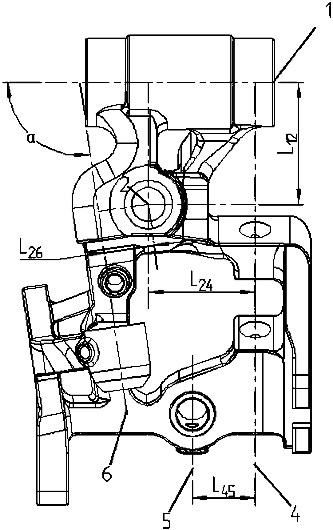
[0048] image 3 Shown is an embodiment of the spatial positi...

Embodiment 2

[0059] A method for machining shaft holes by using the double toothed discs described in Embodiment 1 to drive the shaft hole processing jig of the knotter bracket. The absolute coordinate system setting for processing the knotter bracket on a five-axis numerical control machine tool is set by clamping and punching The double toothed disk of the knotter bracket drives the knotter bracket shaft hole processing fixture to be fixed on the worktable of the five-axis CNC machine tool, and the bolts on the bottom plate 7 of the special fixture are adjusted so that the knotter bracket blank with the grooved plane 23 remains Horizontal, set as the reference plane; use the dial indicator to measure the outer edge of the main shaft hole of the knotter support, determine the axis position of the main shaft hole of the knotter support, set the axis of the main shaft hole of the knotter support as the reference axis, and the reference axis and The reference plane maintains a vertical inters...


PUM


Abstract

The invention provides an axle hole processing clamp and method for a dual-fluted-disc-driven knotter bracket. The axle hole processing clamp comprises a bottom plate, a first positioning block, a regulating bolt, a pressure plate, a mandrel and a third positioning block, wherein the upper end of the first positioning block abuts against one end, with a groove plane, of knotter bracket blank; thelower end of the first positioning block is connected to the bottom plate; one end of the regulating bolt is connected to the bottom plate, and the other end of the regulating bolt abuts against the bottom, with the groove plane, of the knotter bracket blank; one end of the pressure plate is equipped with a through hole, and is pressed in a worm shaft slot hole, and the other end of the pressure plate is connected to the bottom plate; one end of the mandrel passes through a main shaft hole of the knotter bracket blank and is connected to the bottom plate, and the other end of the mandrel is connected to a second positioning block; and the upper end of the third positioning block abuts against the outer edge of the main shaft hole of the knotter bracket, and the lower end of the positioningblock is connected to the bottom plate. The knotter bracket can be clamped once, so that all to-be-processed structure elements of the knotter bracket can be processed out, and therefore, processingtime of the knotter bracket is effectively saved, processing cost is reduced, the knotter bracket yield is remarkably increased, and batch processing problem of the knotter bracket is solved.

Description

technical field [0001] The invention relates to the field of harvesting machinery processing, in particular to a jig and method for processing a shaft hole of a knotter bracket driven by a double toothed disc. Background technique [0002] The D-type knotter is the core component of the square bale baler. It is an integrated automatic device that knots the rope to bind crop straw or pasture. It has the characteristics of complex space structure, difficult manufacturing and high assembly precision. . Chinese invention patent 201510161254.6 has invented a double tooth disc driven knotter, which has the characteristics of reasonable structure, easy processing and assembly, and low manufacturing cost. The knotter bracket is the key part of the double-tooth disc knotter. Other parts of the knotter are fixed to the bracket to complete the knotting movement. The bracket is a special-shaped part with a very complicated structure. There are strict If the processing is inaccurate, i...

Claims


Application Information

Patent Timeline
IPC IPC(8): B23Q3/06B23Q3/16B23B35/00
CPCB23B35/00B23Q3/062B23Q3/16
Inventor 尹建军朱浩彭勇
Owner 泰州市力鼎机械设备有限公司
Why Eureka
Try Eureka