
Luggage handling device

A technology for handling devices and luggage, which is applied in the direction of transportation and packaging, multi-axis trolleys, trolley accessories, etc. It can solve problems such as unstable force application, skewed luggage, property loss, etc., so as to improve handling efficiency, avoid rolling, and save energy. Effect

Inactive Publication Date: 2019-04-05
庄秋瑶
View PDF7 Cites 0 Cited by
  • Summary
  • Abstract
  • Description
  • Claims
  • Application Information

AI Technical Summary

Problems solved by technology

[0002] With the rapid development of science and technology, the phenomenon of urban agglomeration is becoming more and more obvious. Large cities have rich resources such as education, economy, and medical care, and more and more young people gather in large cities; nowadays, the first-tier cities Most of the population is migrants, and most of these migrants live in rented houses or study here; therefore, the living places of these populations are not fixed for a long time, and they often need to change their residences every six months, one to two years, Therefore, the luggage accompanying them needs to be packed and taken away; when white-collar workers in the workplace move or students change dormitories, items will be packed into bags one by one, and the most laborious work is to carry these bags, especially those with less strength. Girls, the bags are full of clothes, books, and sundries. They are heavy, and the surface of the bags is smooth and difficult to grasp, which brings great troubles to moving; such as getting on and off the transport vehicle, transferring bags, and putting bags into the cabinet In the process of carrying, it is difficult to carry; in addition, in the process of carrying bags, it is easy to apply force unstable, causing the bags to skew and roll, causing damage to the internal items, and easily causing certain property losses

Method used


Image

  • Luggage handling device
  • Luggage handling device

Examples


Embodiment

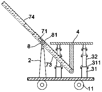
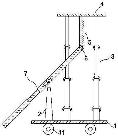
[0015] exist figure 1 , figure 2 In the shown embodiment, the luggage handling device includes a base plate 1, a transfer wheel 11 is arranged on the lower part of the base plate 1, and a support column 2 is arranged above the base plate 1,

[0016] A group of vertical elevating rods 3 are arranged on the base plate 1. In this embodiment, the elevating rods 3 include an outer cylinder 31 and an inner cylinder 32 coaxially sleeved step by step. In the inner cylinder 32 The cylinder wall of the cylinder is equidistantly provided with position-limiting holes arranged along the axis of the cylinder, and a position-limiting buckle 311 is installed on a cylinder end of the outer cylinder 31 connected with the inner cylinder 32; The cylinder wall of 31 is connected by a limit shaft, and the limit buckle 311 can reciprocate and rotate around the limit shaft; the limit buckle 311 is made of permanent magnetic material, and the outer cylinder 31 and inner cylinder 32 are made of ferro...


PUM


Abstract

The invention relates to a luggage handling device, which comprises a base plate, a supporting column is arranged on the base plate, a group of vertical lifting rods are arranged on the base plate, and a bearing plate is fixedly installed at the upper ends of the lifting rods; a transmission rod is installed at the lower part of the bearing plate, and the transmission rod is in axis joint with a driving rod through a rotating shaft; the driving rod is provided with an adjusting sliding groove extending in the rod axis direction, and a supporting shaft is slidably arranged in the adjusting sliding groove, and both ends of the supporting shaft are exposed from the adjusting sliding groove and fixedly connected with the supporting column; a pair of limiting ring pieces are also sleeved on thesupporting shaft, the limiting ring pieces are close to the rod wall of the driving rod, and under the restriction of the limiting ring pieces, the supporting shaft and the limiting ring pieces can only reciprocate and translate along the adjusting sliding groove. The luggage handling device has a novel structure and is convenient to operate, can assist users in easily handling the luggage, lightens the moving burden, ensures the stability and safety of the luggage, and improves the moving efficiency.

Description

technical field [0001] The invention relates to a handling device, in particular, a baggage handling device. Background technique [0002] With the rapid development of science and technology, the phenomenon of urban agglomeration is becoming more and more obvious. Large cities have rich resources such as education, economy, and medical care, and more and more young people gather in large cities; nowadays, the first-tier cities Most of the population is migrants, and most of these migrants live in rented houses or study here; therefore, the living places of these populations are not fixed for a long time, and often need to change their residences every six months, one to two years, Therefore, the luggage accompanying them needs to be packed and taken away; when white-collar workers in the workplace move or students change dormitories, items will be packed into bags one by one, and the most laborious work is to carry these bags, especially those with less strength. Girls, th...

Claims


Application Information

Patent Timeline
IPC IPC(8): B62B3/02B62B3/04B62B5/00
CPCB62B3/02B62B3/04B62B5/00
Inventor 庄秋瑶
Owner 庄秋瑶
Learn More