An automatic control trolley base

An automatic control, trolley technology, applied in the direction of motor vehicles, trolleys, trolley accessories, etc., can solve problems such as the movement of the trolley base, the wear of the brake system, and the inconvenience of use, so as to avoid wear, increase service life, and reduce wear and tear.

Active Publication Date: 2021-11-02
李衍霖
View PDF9 Cites 0 Cited by
  • Summary
  • Abstract
  • Description
  • Claims
  • Application Information

AI Technical Summary

Problems solved by technology

[0003] The existing trolley bases are often stopped by manually braking the brakes, which is very inconvenient to use, and some of the existing braking systems are severely worn during use, and some are unstable when braking, and the trolley base will still move. Phenomenon

Method used


Image

  • An automatic control trolley base
  • An automatic control trolley base
  • An automatic control trolley base

Examples


Embodiment Construction

[0023] The following will clearly and completely describe the technical solutions in the embodiments of the present invention with reference to the accompanying drawings in the embodiments of the present invention. Obviously, the described embodiments are only some, not all, embodiments of the present invention. Based on the embodiments of the present invention, all other embodiments obtained by persons of ordinary skill in the art without making creative efforts belong to the protection scope of the present invention.

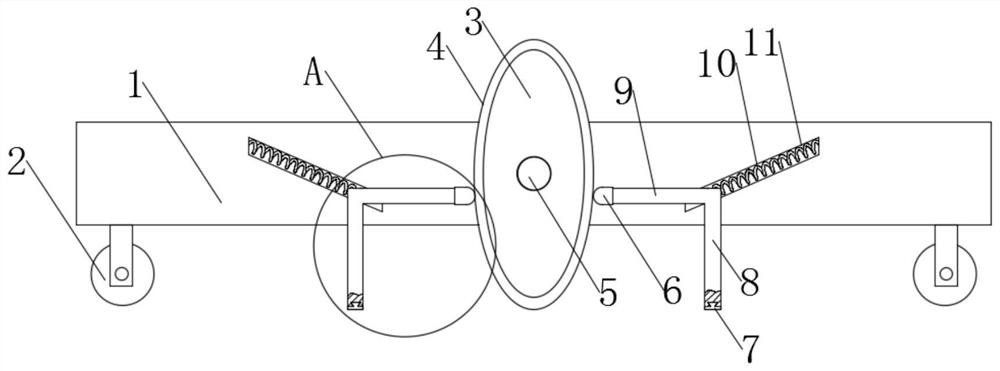
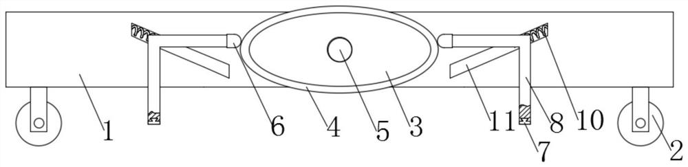
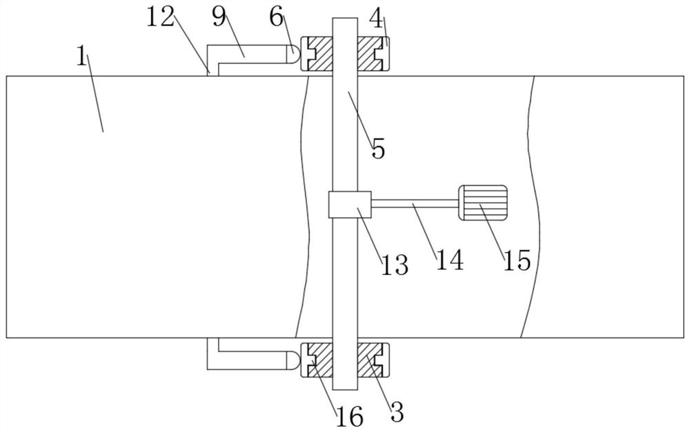
[0024] see Figure 1 to Figure 4 , the present invention provides a technical solution: an automatic control trolley base, comprising a trolley base body 1, a moving wheel 2, a brake wheel 3 and a brake stabilizer bar 8, the trolley base body 1 has a rectangular plate-like structure, and the trolley base body 1 The four corners of the lower surface are equipped with movable wheels 2, and the two sides of the middle position of the trolley base body 1 are movab...


PUM


Abstract

The invention discloses an automatic control trolley base, which comprises a trolley base body, a moving wheel, a brake wheel and a brake stabilizer bar. In the present invention, the motor is indirectly driven to rotate the brake wheel. The long diameter of the brake wheel is greater than the vertical distance from the bottom surface of the moving wheel to the middle position of the brake wheel. When the long diameter of the brake wheel is vertical, the bottom of the brake wheel contacts the ground and will move The wheel is overhead to achieve the function of fixing the base body of the trolley, achieve the braking effect, and is easy to control and use. In the present invention, when the brake wheel is in the braking state, the spring spring uses the elastic force to push the moving rod, and then the rubber sheath at the end of the control rod is in contact with the In the middle of the brake wheel, the anti-slip mat at the bottom of the brake stabilizer bar is in contact with the ground, reaching three points of contact with the ground and stabilizing the braking effect.

Description

technical field [0001] The invention relates to the technical field of automatic control trolley base, in particular to an automatic control trolley base. Background technique [0002] The trolley base is a base that supports the trolley as a whole. There are also moving wheels on the base. The mobile wheels play the role of moving the trolley to facilitate the movement and transportation of the trolley. [0003] The existing trolley bases are often stopped by manually braking the brakes, which is very inconvenient to use, and some of the existing braking systems are severely worn during use, and some are unstable when braking, and the trolley base will still move. Phenomenon. [0004] For this reason, we propose an automatic control trolley base to solve the above-mentioned drawbacks well. Contents of the invention [0005] The purpose of the present invention is to provide an automatic control trolley base to solve the problems raised in the above-mentioned background ...

Claims


Application Information

Patent Timeline
Patent Type & Authority Patents(China)
IPC IPC(8): B62B5/04
CPCB62B5/049
Inventor 李衍霖
Owner 李衍霖
Why Eureka
Try Eureka