Suspension friction transport trolley guide device

A technology of guiding device and trolley, which is used in conveyors, mechanical conveyors, transportation and packaging, etc., to achieve the effect of reducing the amplitude of left and right swings

Active Publication Date: 2019-04-05
李楠
View PDF8 Cites 0 Cited by
  • Summary
  • Abstract
  • Description
  • Claims
  • Application Information

AI Technical Summary

Problems solved by technology

[0004] Above-mentioned prior art is very general, and its shortcoming is that the supporting point of guide roller 12a is just on the side trolley of I-beam lower beam, and support force arm only has guide roller radius R, and T-shaped hollow track and guide roller The guide constraints between 12a are only constrained near the track, while the crane body with a greater distance below is less constrained by the guide rollers 12a

Method used


Image

  • Suspension friction transport trolley guide device
  • Suspension friction transport trolley guide device
  • Suspension friction transport trolley guide device

Examples


Embodiment 1

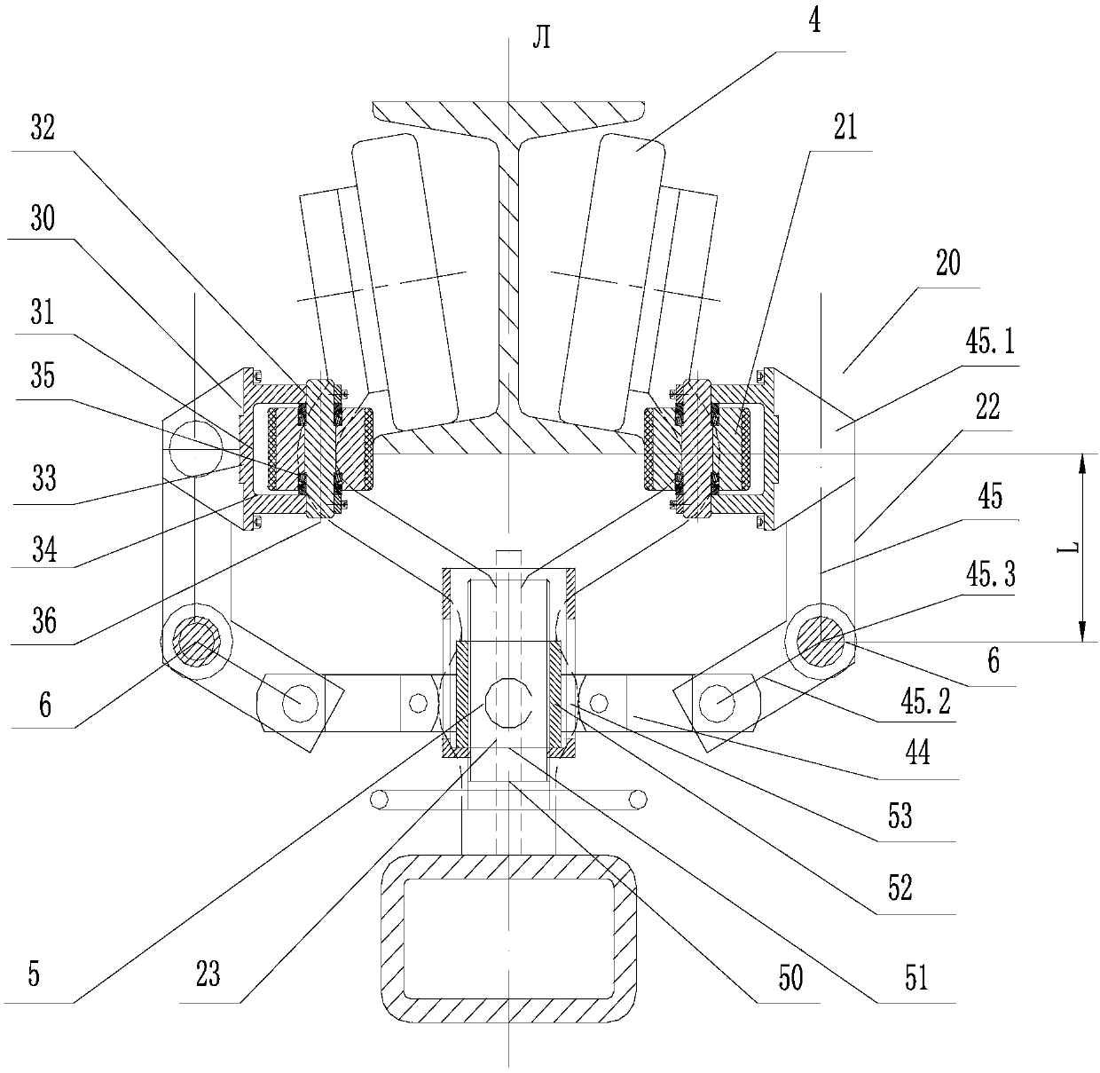
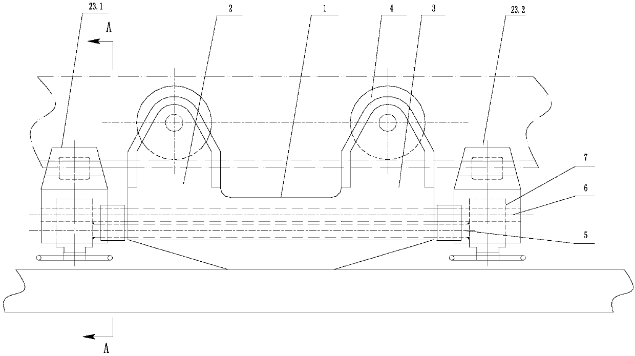
[0047] As shown in the figure, a guiding device for a trolley transported by a suspension friction conveyor includes a trolley body 1, a front wheel frame 2 and a rear wheel frame 3, and the front wheel frame 2 and the rear wheel frame 3 are integrally connected to the trolley body 1 The cross-section of the trolley body 1 is a Y-shaped structure arranged symmetrically with the mid-plane datum Л, and the mid-plane datum Л is the cross-section of the straight wall centerline of the Y-shaped structure; the lower beam of the I-beam extends into the Y-shaped structure In the opening of the front wheel frame 2, the two sides of the rear wheel frame 3 are respectively rotatably provided with a pair of road wheels 4, and the distance between the axis of the road wheels of the front wheel frame 2 and the rear wheel frame 3 is the distance between the front and rear of the road wheels L0; the trolley body 1 The left and right sides are axially symmetrical and can be opened and closed wi...

Embodiment 2

[0057] On the basis of Embodiment 1, a lower beam guiding and pressing mechanism 60 is added, and the specific structure is as follows:

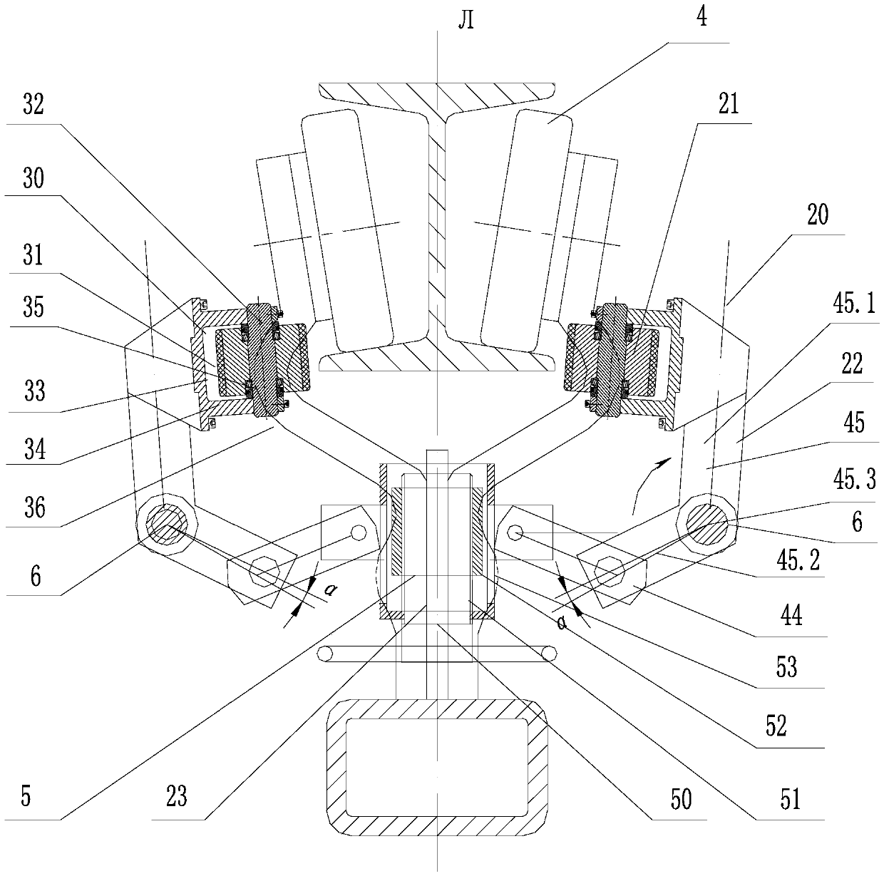
[0058] The front and rear ends of the triangular frame structure 10 are respectively provided with the lower beam guiding and pressing mechanism 60, and the lower beam guiding and pressing mechanism 60 includes a bottom guide wheel 64, between the rotating shaft of the bottom guide wheel 64 and the second main shaft 6 Pivotally connect the left arm 61 and the right arm 62, pivotally connect the middle arm 63 between the rotating shaft of the bottom guide wheel 64 and the first main shaft 5, the first main shaft 5 is provided with a chute 66, and the middle arm 63 The rotating shaft is slidingly arranged in the chute 66; it also includes a hook 67, one end of the hook 67 is rotatably fixed on the first main shaft 5, and the hook 67 is engaged with the rotating shaft of the middle arm 63 to lock it in the chute position in .

[0059] The trol...


PUM


Abstract

The invention discloses a suspension friction transport trolley guide device. The device comprises a trolley body and triangular framework structures, wherein the triangular framework structures are symmetrically and fixedly connected to the trolley body according to a middle surface reference axis, and the triangular framework structures are symmetrically provided with guide wheel mechanisms in an opening and closing mode according to the middle surface reference axis; each guide wheel mechanism comprises a guide wheel, a connecting rod mechanism and an abutting mechanism, wherein the guide wheel is rotationally fixed on the connecting rod mechanism, and the abutting mechanism is fixedly connected to the connecting rod mechanism; and the guide wheel mechanisms are switched between the abutting position and the expanding position, at the abutting position, the guide wheels abut against the side edges of the lower beams of I-shaped beams, the abutting mechanisms apply abutting force tothe connecting rod mechanisms, and the connecting rod mechanisms are used for converting the abutting force into abutting moments to abut against the guide wheels. According to the suspension frictiontransport trolley guide device, the left and right swinging amplitude of the trolley body on the I-shaped beams is greatly reduced.

Description

technical field [0001] The invention relates to the technical field of friction conveying systems, in particular to a guiding device for a suspended friction conveying trolley. Background technique [0002] The chassis line and door line conveying in the assembly workshop of the complete vehicle factory. At present, many complete vehicle factories adopt the suspension friction conveying line. The suspension friction conveying line uses the principle of friction drive to complete the conveying of the workpiece through the static friction force between the power device (friction wheel) and the bearing medium (slinger) of the workpiece. Suspension friction conveying is that the friction wheels set at intervals press against the middle push rod. Although it can be driven without idle distance, because the conveyed object is hung on the middle push rod for conveying, there is an error caused by the sliding direction and sliding force, which makes the conveying Unstable and swayi...

Claims


Application Information

Patent Timeline
IPC IPC(8): B65G35/00
CPCB65G35/00
Inventor 李楠
Owner 李楠
Why Eureka
Try Eureka