
Ship engine

A marine engine and cylinder technology, which is applied to machines/engines, mechanical equipment, etc., can solve the problems of complex crankshaft structure, easy-to-break marine engine thermal efficiency, manufacturing difficulties, etc., to improve thermal efficiency, reduce effective rotation radius, and reduce vibration. and friction and other losses

Active Publication Date: 2019-04-16
张保卫 +1
View PDF6 Cites 0 Cited by
  • Summary
  • Abstract
  • Description
  • Claims
  • Application Information

AI Technical Summary

Problems solved by technology

[0005] In order to overcome the problems in the related art at least to a certain extent, the purpose of the present application is to provide a marine engine, which can solve the problem of the design limitation of the length-to-diameter ratio of the existing marine engine and the complex and difficult manufacture of the crankshaft structure, which is easy to break and Low Thermal Efficiency of Existing Marine Engines

Method used


Image

  • Ship engine
  • Ship engine
  • Ship engine

Examples


Embodiment 1

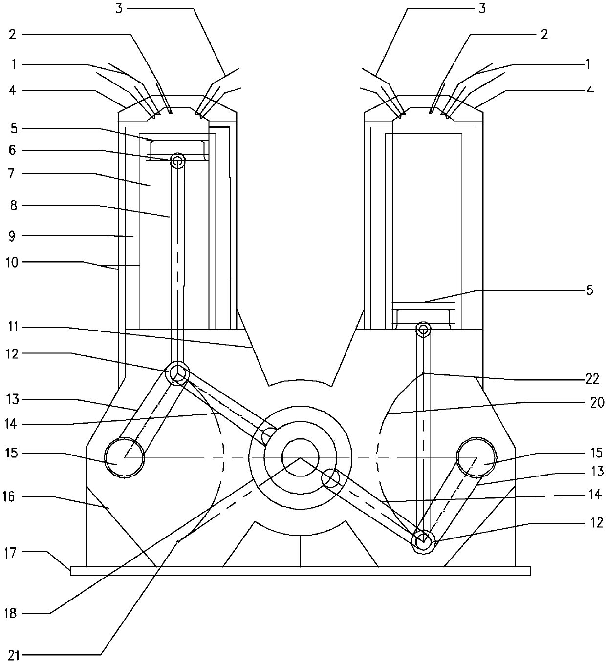
[0070] Embodiment 1, the crank diameter of this marine engine can be 1260mm, the diameter of cylinder 7 can be 960mm, the length of piston rod 8 can be 3275mm, the length of crankshaft connecting rod 14 can be 1514mm, and the length of swing rod 13 can be 1439mm, thus The obtained piston stroke is 2600mm, the ratio of the stroke to the diameter of the crankshaft 18 is 2.064, and the aspect ratio of the cylinder 7 is 2.708.

Embodiment 2

[0071] Embodiment 2, the crank diameter of this marine engine can be 892mm, the diameter of cylinder 7 can be 880mm, the length of piston rod 8 can be 2318mm, the length of crankshaft connecting rod 14 can be 1119mm, and the length of swing rod 13 can be 1011mm, thus The obtained piston stroke is 1840 mm, the ratio of the stroke to the diameter of the crankshaft 18 is 2.063, and the aspect ratio of the cylinder 7 is 2.091.

Embodiment 3

[0072] Embodiment 3, the crank diameter of engine can be 703mm, the diameter of cylinder 7 can be 860mm, the length of piston rod 8 can be 2641mm, the length of crankshaft connecting rod 14 can be 1000mm, the length of pendulum 13 can be 1411mm, thus draws The piston stroke is 1840mm, the ratio of the stroke to the diameter of the crankshaft 18 is 2.617, and the aspect ratio of the cylinder 7 is 2.140.


PUM

PropertyMeasurementUnit
Diameteraaaaaaaaaa
Diameteraaaaaaaaaa

Abstract

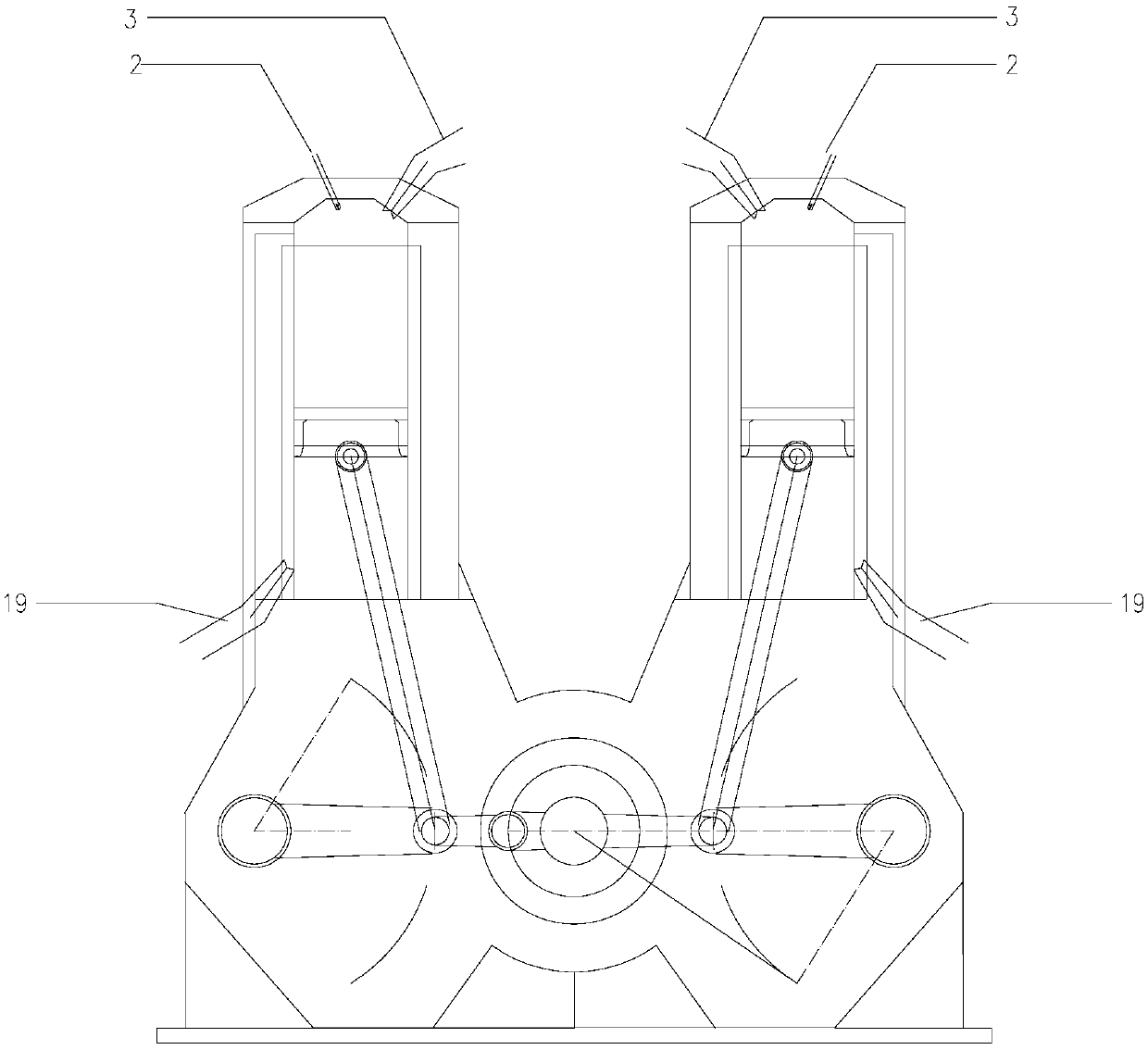
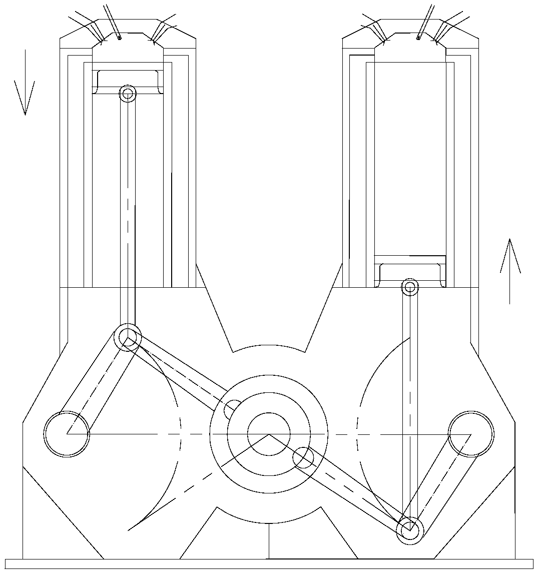
The invention relates to the technical field of engines, and discloses a ship engine. The ship engine comprises cylinders, piston rods connected with pistons of the cylinders, a bent shaft, bent shaftconnecting rods connected with a crank of the bent shaft, a bent shaft box for installing the bent shaft, and oscillating bars with the first ends rotationally connected to the inner wall of the bentshaft box, wherein the second end of each oscillating bar is connected with the corresponding piston rod and the corresponding bent shaft connecting rod to one point. Each piston moves to the lower stop point from the upper stop point and moves to the upper stop point from the lower stop point, the corresponding piston rod drives the corresponding bent shaft to rotate by two circles, and when each piston runs to the middle position of the connecting line of the upper stop point and the lower stop point, the corresponding oscillating bar and the corresponding bent shaft connecting rod are located on the same straight line. Under the situation that the pistons run at low speed, the bent shafts can rotate with the two-time angular speed, the larger angular momentum is transmitted, the higherbent shaft rotation speed can be achieved for the low-speed piston motion, and the heat efficiency of the engine is improved. Through the arrangement, the problems that an existing ship engine bent shaft is complex in structure, difficult to manufacture and prone to fracture, and the heat efficiency of a ship engine is low are solved.

Description

technical field [0001] The present application relates to the technical field of engines, and more specifically, relates to a marine engine. Background technique [0002] An engine, also known as an engine, is a machine that converts another form of energy, usually chemical energy, into mechanical energy, such as a gasoline engine. Because gasoline has low viscosity and evaporates quickly, the gasoline injection system can be used to inject gasoline into the cylinder, and after being compressed to a certain temperature and pressure, it is ignited with a spark plug to make the gas expand and do work, so as to convert chemical energy into mechanical energy. The motion principle of the engine is to convert the linear reciprocating motion of the piston in the cylinder body into a rotary motion by the crankshaft to output power. The distance that the piston of the engine travels from one limit position to another limit position is called a stroke. Because the gasoline engine is...

Claims


Application Information

Patent Timeline
IPC IPC(8): F02B75/18F02B75/32
CPCF02B75/18F02B75/32
Inventor 张保卫张杰
Owner 张保卫
Learn More