

Tubular shroud ring type electric wire damping device and mounting method thereof
A shock absorbing device and tubular technology, applied in the direction of mechanical vibration damping device, etc., can solve the problems of high cost and complex structure, and achieve the effect of low cost, simple structure and vibration reduction.
Inactive Publication Date: 2015-06-03
STATE GRID HENAN ELECTRIC POWER COMPANY ANYANG POWER SUPPLY
View PDF9 Cites 2 Cited by
- Summary
- Abstract
- Description
- Claims
- Application Information
AI Technical Summary
Problems solved by technology
[0005] Aiming at the problems of complex structure and high cost of the transmission line anti-dancing shock absorbing device in the prior art
Method used
View moreImage
Smart ImageViewing Examples

Examples
Embodiment Construction
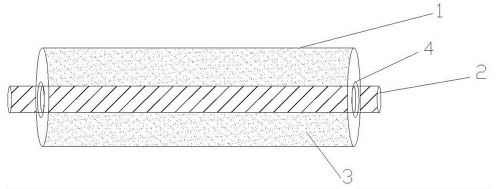
[0011] Such as figure 1 As shown, a tubular hoop-type wire shock absorber includes a tubular shell 1 for damping, and a sealing rubber sheet 4 arranged at both ends of the tube. The rubber sheet 4 is provided with a wire penetration hole, and the wire 2 The inside of the shell is injected with rubber 3. The rubber 3 is silica gel, which can be effectively prevented from rotating around the axis through the fixing effect of injection molding silica gel.
[0012] The installation method of the tubular hoop-type electric wire shock absorber is that after the lead wire 2 is passed through the penetration holes of the rubber sheet 4 at both ends of the shell, the silica gel is poured into it.
Login to View More PUM
 Abstract
The invention relates to a tubular shroud ring type electric wire damping device, which comprises a tubular casing with a damping function, and sealing rubber sheets, wherein the sealing rubber sheets are arranged at the two ends of a tube, a conducing wire through hole is formed in each rubber sheet, and silica gel is injected into the casing in which a conducting wire penetrates. The tubular shroud ring type electric wire damping device has the advantages that when the conducting wire suffers from the action of external force along different directions, the vibration along each direction can be reduced by the silica gel in the casing; the rotation around the axis is effectively prevented under the fixing action of injection molding silica gel.
Description
technical field [0001] The invention relates to an anti-vibration device for a power transmission line, in particular to a tubular hoop-type electric wire anti-vibration device and an installation method thereof. Background technique [0002] The power transmission line is erected in the field, and it is often affected by the wind to cause shaking and vibration. In some cases, even if it is not a windy day, the vibration will become more and more intense due to resonance, and the amplitude will become larger and larger, eventually causing The transmission line is disconnected, the equipment is damaged, and the normal power transmission is affected. [0003] The current anti-vibration and anti-dance devices for transmission lines mainly include pre-twisted wires and center of gravity hammers, etc., but the anti-dance effect of pre-twisted wires is poor. If the center of gravity hammer is used, too many will increase the burden on the transmission line, which is also a hazard ...
Claims
Login to View More Application Information
Patent Timeline
 Patent Type & AuthorityApplications(China)
IPC IPC(8): H02G7/14
CPCH02G7/14
Inventor邹启群王晓宁俎洋辉张琳
OwnerSTATE GRID HENAN ELECTRIC POWER COMPANY ANYANG POWER SUPPLY