Feeding device

A feeding device and material technology, applied in the direction of conveyor objects, transportation and packaging, etc., can solve problems such as high cost and complex design

Active Publication Date: 2019-04-05
TCL KING ELECTRICAL APPLIANCES HUIZHOU
View PDF5 Cites 4 Cited by
  • Summary
  • Abstract
  • Description
  • Claims
  • Application Information

AI Technical Summary

Problems solved by technology

The design of the above feeding equipment is complicated and the cost is high

Method used


Image

  • Feeding device
  • Feeding device
  • Feeding device

Examples


Embodiment Construction

[0037] The following will clearly and completely describe the technical solutions in the embodiments of the present invention with reference to the accompanying drawings in the embodiments of the present invention. Obviously, the described embodiments are only part of the embodiments of the present invention, not all of them. Based on the embodiments of the present invention, all other embodiments obtained by persons of ordinary skill in the art without creative efforts fall within the protection scope of the present invention.

[0038] It should be noted that if there is a directional indication (such as up, down, left, right, front, back...) in the embodiment of the present invention, the directional indication is only used to explain the position in a certain posture (as shown in the accompanying drawing). If the specific posture changes, the directional indication will also change accordingly.

[0039] In addition, if there are descriptions involving "first", "second" and ...


PUM


Abstract

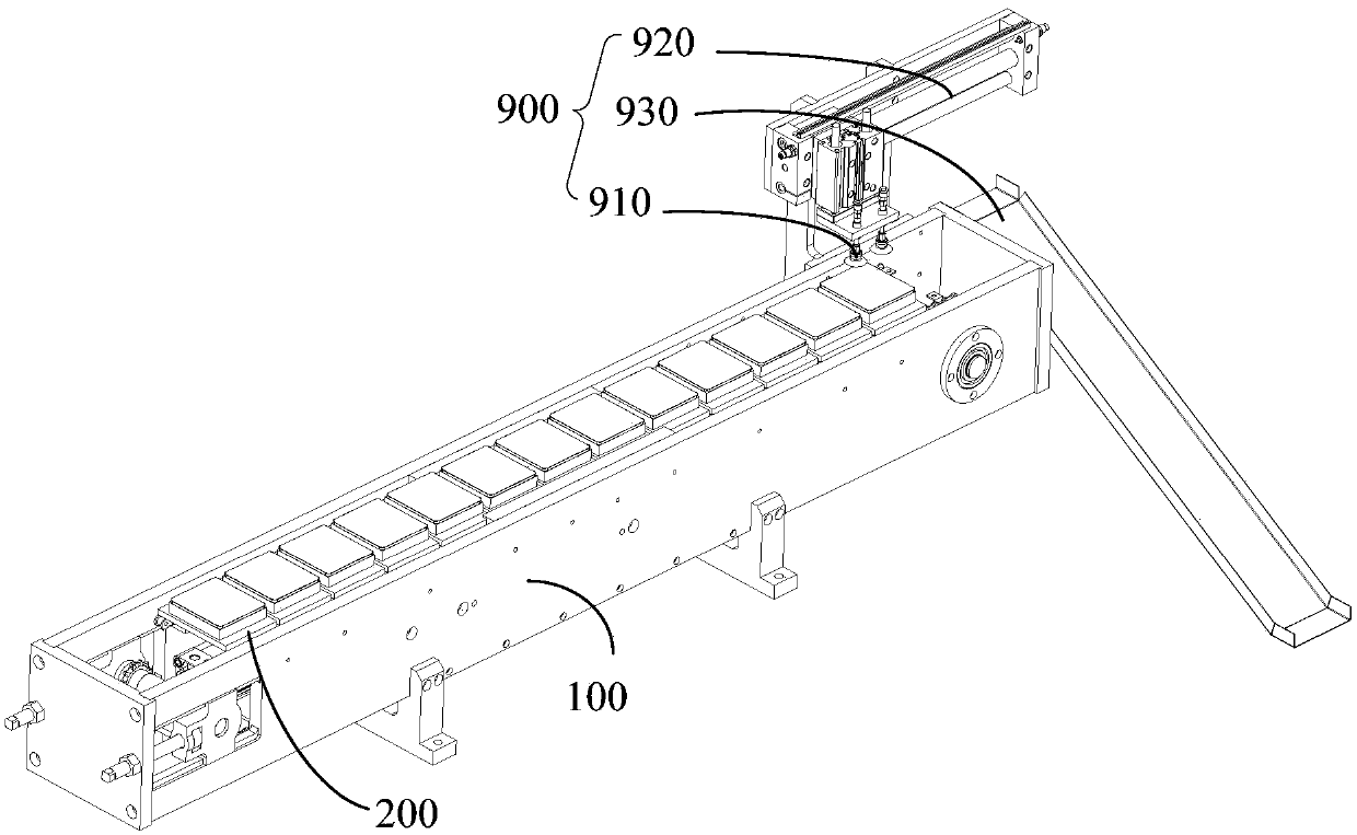
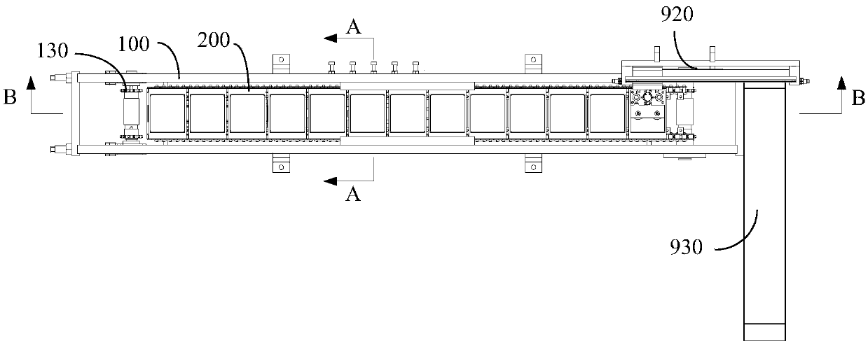
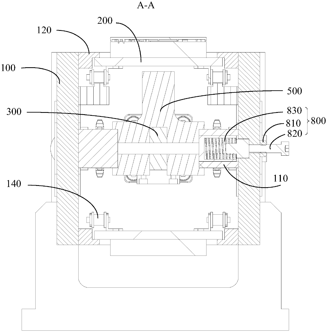
The invention discloses a feeding device. The feeding device comprises a machine base, multiple supporting plates arranged side by side and linked, a pulling rod, an inserting pin, a sliding block anda driving part connected with the pulling rod; the supporting plates, the pulling rod, and the sliding block are in sliding connection with the machine base, each supporting plate is provided with alimiting hole, the pulling rod comprises a slope part, one of the sliding block and the pulling rod is provided with a strip sliding hole, and the other of the sliding block and the pulling rod comprises a stop pin inserted into the sliding hole, the inserting pin is arranged on the sliding block in a sliding manner, one end of the inserting pin is in abut joint with the slope part and can slide relative to the slope part, the other end of the inserting pin extends towards a limiting hole, under driving of the driving part, the pulling rod moves in a reciprocating manner, the pulling rod drives the inserting pin to be inserted into or separated from the limiting hole through the slope part, the pulling rod can drive the sliding block to intermittently move through the stop pin, the slidingblock drives the inserting pin to be selectively aligned with one supporting plate. According to the technical scheme, the feeding device is low in cost, and feeding is achieved at an equal step.

Description

technical field [0001] The invention relates to the technical field of mechanical equipment, in particular to a feeding device. Background technique [0002] At present, many feeding equipment usually use stepping motors in order to realize equidistant transportation, and when positioning is required, most of them rely on cylinders to lift the limit column to limit the pallet on which the workpiece is placed. The above feeding equipment is complex in design and expensive. Contents of the invention [0003] The main purpose of the present invention is to propose a feeding device, aiming at reducing equipment cost. [0004] In order to achieve the above object, the feeding device proposed by the present invention includes: [0005] Machine base; [0006] A plurality of pallets, the pallets are used to place materials, and the pallets are slidably connected to the machine base; multiple pallets are arranged side by side and linked together, and each pallet has a limit hole...

Claims


Application Information

Patent Timeline
Patent Type & Authority Applications(China)
IPC IPC(8): B65G47/91B65G47/82
CPCB65G47/82B65G47/912
Inventor 胡爱民潘德灼高文周龙会平呙雄郭国军段文军史延广吴和强
Owner TCL KING ELECTRICAL APPLIANCES HUIZHOU
Why Eureka
Try Eureka