
Device for adjusting areas of orifices of lubricating oil pipelines

A technology of area adjustment and orifice, applied in valve devices, sliding valves, engine components, etc., to achieve strong work continuity and save time and cost.

Inactive Publication Date: 2019-04-05
AECC SHENYANG ENGINE RES INST
View PDF6 Cites 7 Cited by
  • Summary
  • Abstract
  • Description
  • Claims
  • Application Information

AI Technical Summary

Problems solved by technology

[0005] The purpose of this application is to provide a lubricating oil pipeline orifice area adjustment device to solve at least one of the above-mentioned problems

Method used


Image

  • Device for adjusting areas of orifices of lubricating oil pipelines
  • Device for adjusting areas of orifices of lubricating oil pipelines
  • Device for adjusting areas of orifices of lubricating oil pipelines

Examples


Embodiment Construction

[0021] In order to make the purpose, technical solution and advantages of the application more clear, the technical solution in the embodiment of the application will be described in more detail below in conjunction with the drawings in the embodiment of the application. In the drawings, the same or similar reference numerals denote the same or similar elements or elements having the same or similar functions throughout. The described embodiments are some, but not all, embodiments of the application. The embodiments described below by referring to the figures are exemplary, and are intended to explain the present application, and should not be construed as limiting the present application. Based on the embodiments in this application, all other embodiments obtained by persons of ordinary skill in the art without creative efforts fall within the protection scope of this application. Embodiments of the present application will be described in detail below in conjunction with th...


PUM


Abstract

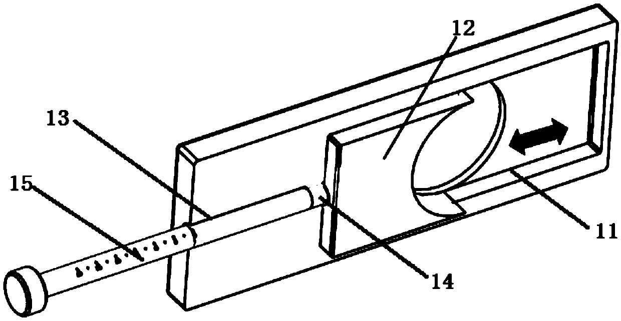
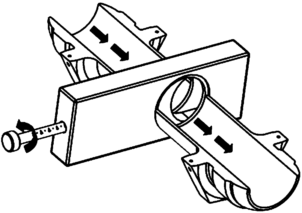
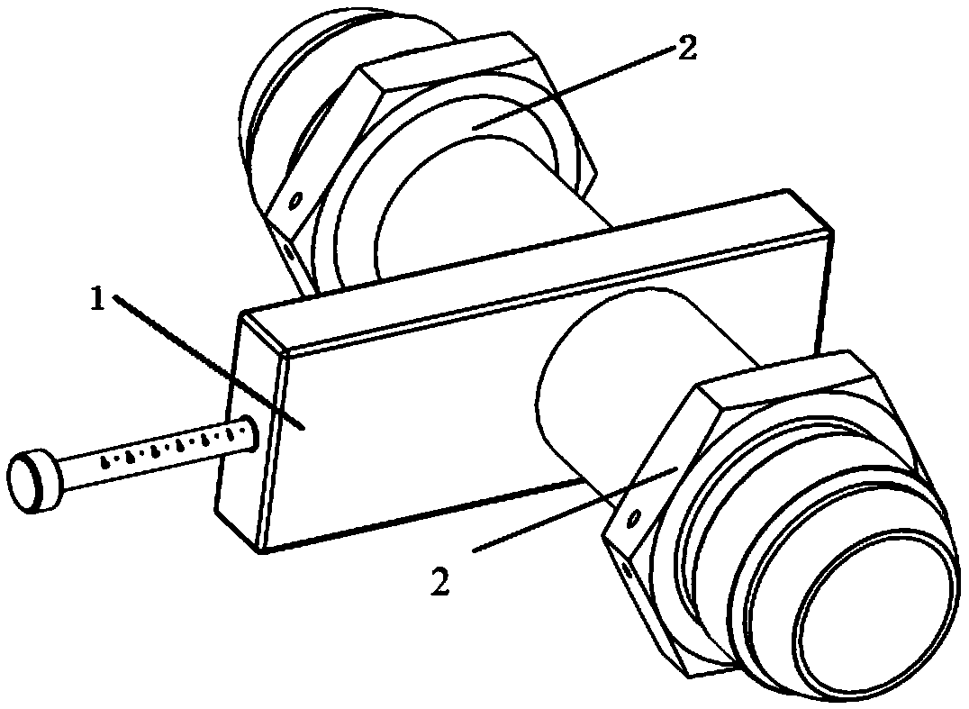
The invention discloses a device for adjusting the areas of orifices of lubricating oil pipelines, and belongs to the technical field of design of aero-engine lubricating oil systems. The device comprises an adjusting pipeline arranged between the lubricating oil pipelines, and an adjusting valve. A channel is formed in the adjusting valve, a sliding way is arranged on the side portion of the channel, an adjusting plate (12) is slidingly arranged in the sliding way (11), when the adjusting plate (12) slides in the sliding way, the adjusting plate can at least partially block a through hole, athreaded hole (13) penetrating out of the adjusting valve is formed in one end of the sliding way in the sliding direction of the adjusting plate (12), a magnetic threaded rod (15) is screwed into thethreaded hole, a magnetic cylinder (14) is arranged at the end, stretching into the threaded hole (13), of the magnetic threaded rod (15), and the adjusting plate (12) is magnetic, and is attracted on the magnetic cylinder (14). Fluid in the lubricating oil system pipelines can be subjected to throttle control without splitting the lubricating oil pipelines in the test process, , and the purposeof throttling lubricating oil flow ways or air flow ways is achieved.

Description

technical field [0001] The application belongs to the technical field of aero-engine lubricating oil system design, and in particular relates to a device for adjusting the area of ​​an orifice in a lubricating oil pipeline. Background technique [0002] During the test run or test of the engine or tester on the ground bench, the lubricating oil system must ensure stable oil supply, oil return and ventilation, and the lubricating oil consumption should meet the operating requirements. Therefore, according to the test run or test status, it is necessary to install throttling orifice plates in the pipelines (oil supply, oil return, and ventilation), and to constantly replace throttling orifice plates with different throttling areas to achieve smooth oil flow or air flow. The purpose of road throttling is to meet the requirements of the engine or tester. [0003] At present, during the test run or test process, when the throttle orifice is installed, the test run or test needs ...

Claims


Application Information

Patent Timeline
Patent Type & Authority Applications(China)
IPC IPC(8): F16K3/02F16K3/30F16K3/312
CPCF16K3/0218F16K3/30F16K3/312
Inventor 迟延飞宋冠麟郁丽
Owner AECC SHENYANG ENGINE RES INST
Learn More