A ceiling LED lamp shade with an adjustable structure
A technology for LED lamps and lampshades, which is applied to lampshades, parts of lighting devices, semiconductor devices of light-emitting elements, etc., can solve the problems of affecting the moving effect, offset, and insufficient stability, and achieve convenient replacement and reduce replacement costs. Hassle and cost, the effect of reducing discomfort
- Summary
- Abstract
- Description
- Claims
- Application Information
AI Technical Summary
Problems solved by technology
Method used
Image
Examples
Embodiment 1
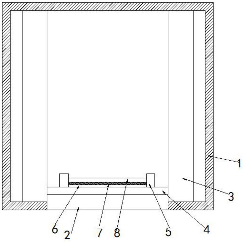
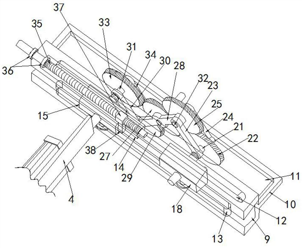
[0027] Example 1, such as figure 1 with 4As shown, including the lampshade body 1, one side of the lamp cover body 1 opens an opening 2, and both sides of the lamp cover body 1 are fixedly mounted with a relative moving structure 3, between the two-sided moving structure 3 The mounting plate 4 that is fixed to the external lamp bolt is fixed and the opening 2 is attached, and the mounting plate 4 is away from the openings 2 side ends, and there is a block 5, two side cards. A substrate 6 is mounted between the block 5 and near the mounting plate 4, and a circuit board 7 is mounted on the substrate 6, and a detachable LED flap is mounted on the circuit board 7; wherein The moving structure 3 includes a fixed panel 9 mounted on both sides of the lamp cover body 1 and relative types of type U-shaped plate 9 and a fixed plate 1 10 that is fixed to the central portion of the U-plate plate 9, the fixed plate one 10 The top screw fixes a fixed plate 2 11, the U-shaped plate 9 and the ce...
Embodiment 2
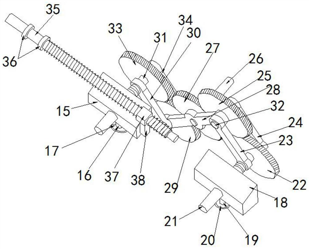
[0028] Example 2, such as Figure 2-4 As shown, the fixed column 2 18 is fixed to one end of the U-shaped trough provided in the side of the U-plate plate 9 and close to one end of the opening 2, and the central portion of the fixed column 2 18 is inserted with the shaft. The rod 21, the shaft two 21 and the end of the fixing plate 2 11 extend through the hollow groove 12 to the side of the hollow groove 12 and a connecting rod 12, the connecting rod one 24 and close to the fixed column 2 18 and a gear 122 is provided on the shaft 212, the gear one 22 and away from one side of the connecting rod 24 and is located in the shaft. The surface of the second 21 is provided with a connecting rod 2 23, wherein the connecting rod 23 and the connecting rod 24 and away from one end of the shaft 21, there is a shaft 4 32, The central portion of the shaft 4 32 is provided with a gear 2 25 with the gear 122, and the surface of the shaft 4 32 is connected to the end sleeve close to the connecting...
Embodiment 3
[0029] Example 3, Figure 2-4 As shown, the bottom screw of the slider 37 fixes a strut 38, and the side bolt of the strut 38 is fixed to the phase side end of the fixed column 12, and a set of fixed ring 36 is located in the One end of the inner wall of the groove 14 and the side end of the U-shaped plate 9 facilitates the slider between the slider 37 and the screw 35, and the slider 37 and the opposite of the screw 35 are inner threads, so that support When the slider 37 is moved, the slider 37 can be moved on the screw, which can achieve both movement and function of stabilizing support.
[0030] Specific workflow: The opening 2 is opened at the top of the lampshade body 1, by mounting the outer lamp holder on the mounting plate 4, by means of a wire in the lamp cover body 1, and moving the moving structure 3 and the outer wall switch by the wire Connecting, the gear one 22 is rotated under the control of the switch, and the gear one 22 drives the gear 25 and the gear three 27, ...
PUM
 Abstract
Description
Claims
Application Information
 - R&D
- Intellectual Property
- Life Sciences
- Materials
- Tech Scout
- Unparalleled Data Quality
- Higher Quality Content
- 60% Fewer Hallucinations
Browse by: Latest US Patents, China's latest patents, Technical Efficacy Thesaurus, Application Domain, Technology Topic, Popular Technical Reports.
© 2025 PatSnap. All rights reserved.Legal|Privacy policy|Modern Slavery Act Transparency Statement|Sitemap|About US| Contact US: help@patsnap.com


