
Operating device for switching devices

A technology for switching electrical appliances and operating devices, which is applied to electrical switches, circuits, electrical components, etc., can solve the problems affecting the normal and safe switching of control circuits, misoperation of two sets of switching electrical appliances, and arc damage to operators, to ensure safety and reliability. Reliability, enhanced electrical insulation and protection, and the effect of eliminating safety hazards

Pending Publication Date: 2019-04-05
KEDU ELECTRIC CO LTD
View PDF0 Cites 0 Cited by
  • Summary
  • Abstract
  • Description
  • Claims
  • Application Information

AI Technical Summary

Problems solved by technology

[0004] Therefore, the technical problem to be solved by the present invention is to overcome the fact that the two groups of switching devices in the prior art need to rely on people to directly operate their handles to realize the switching operation, which is easy to cause the operator to be injured by the arc, and it is easy to cause the two groups of switching devices to be misused. Operation, affecting the normal safe switching of control lines and loads, there is a problem of greater safety hazards, so as to provide a way to independently control the opening and closing of two sets of switching devices without mutual interference, avoiding the operator from being hurt by the arc and ensuring control Safe and normal switching of lines, safe and reliable switch electrical operating device

Method used


Image

  • Operating device for switching devices
  • Operating device for switching devices
  • Operating device for switching devices

Examples


Embodiment 1

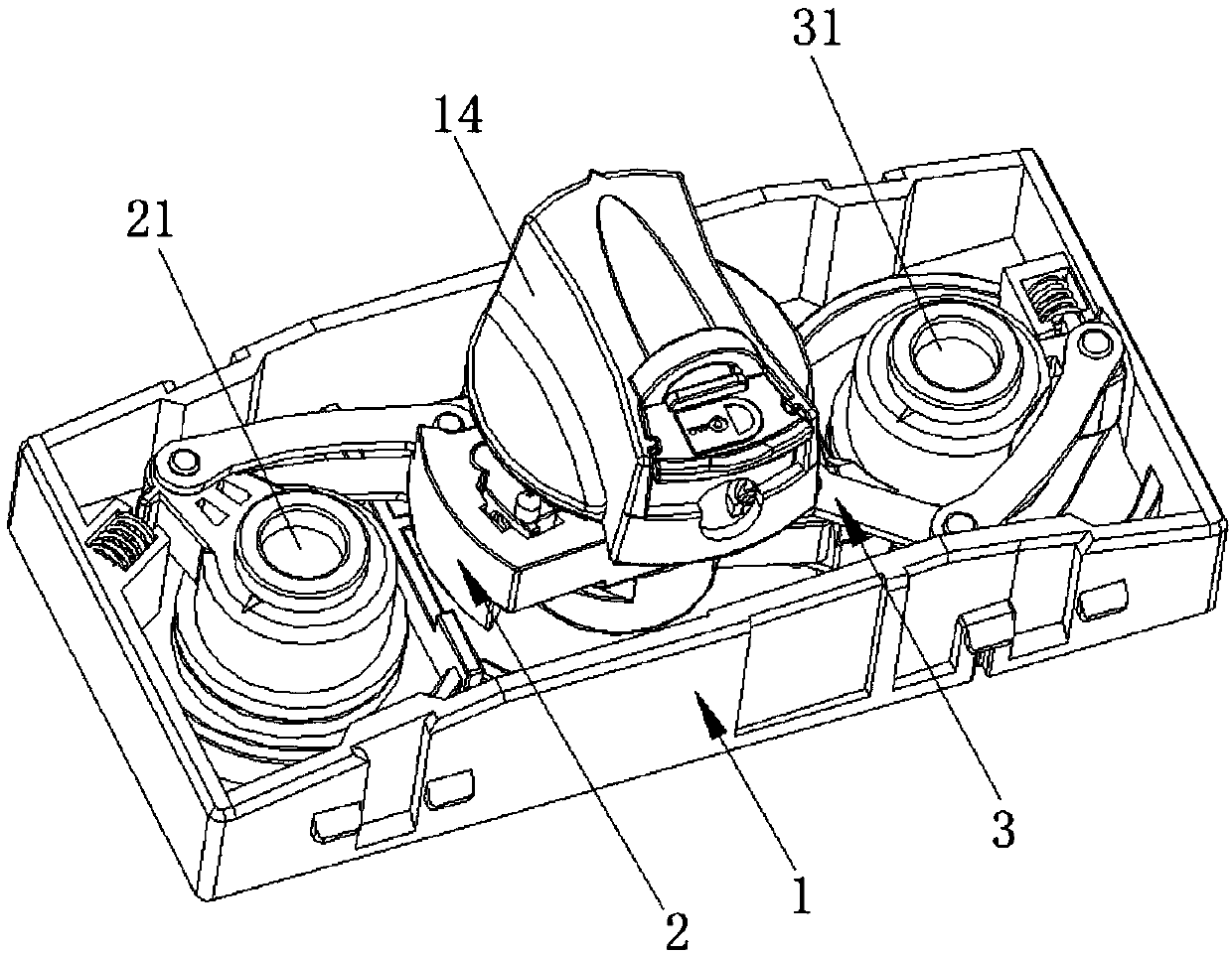
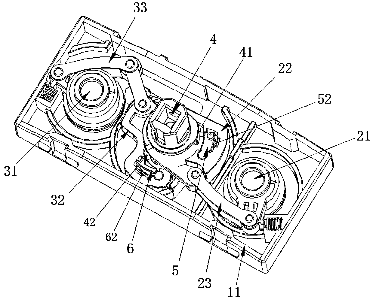
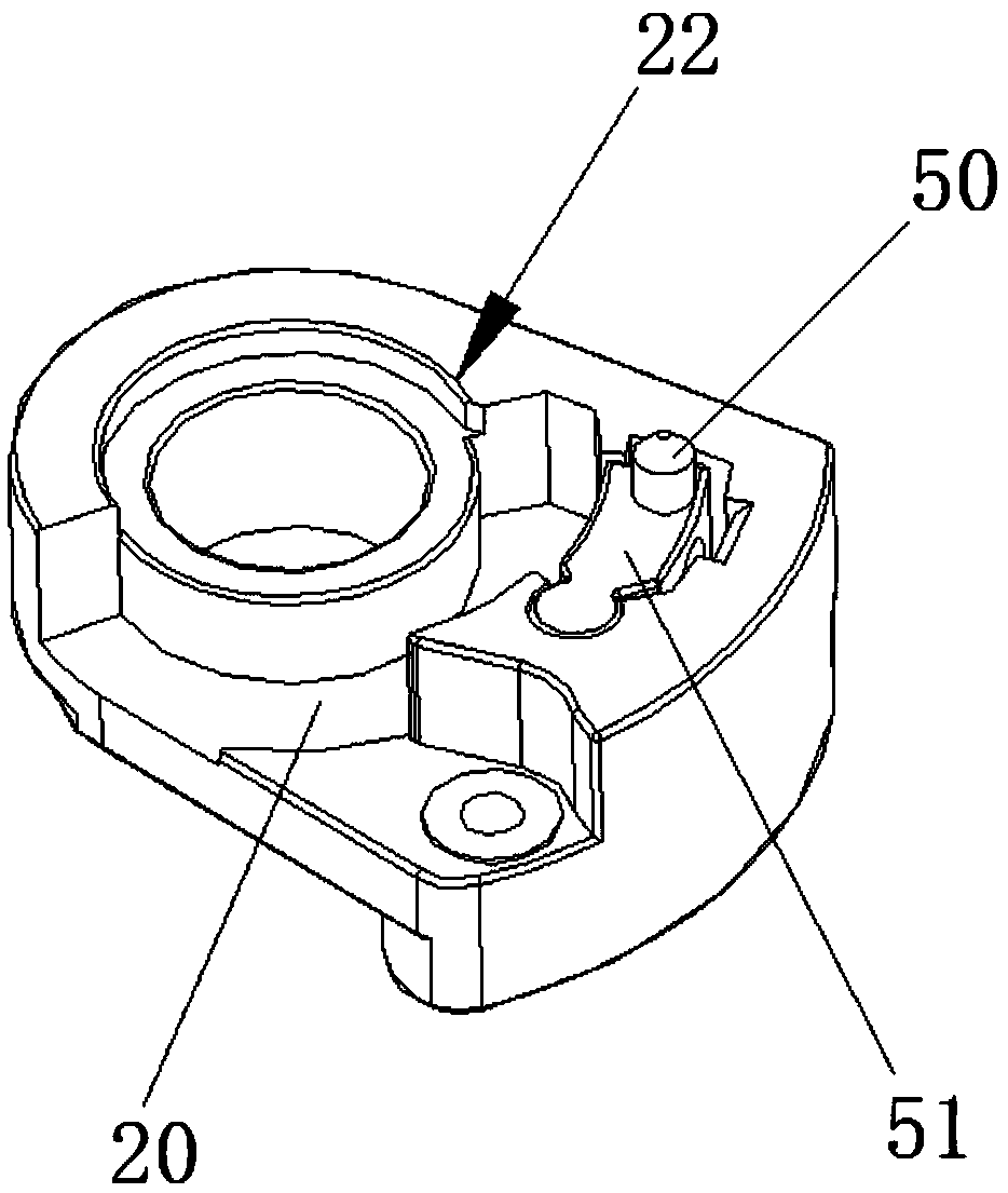
[0054] The present invention provides as Figure 1-12 A switching device operating device is shown, which is used to drive and control two groups of switching devices to turn on or off respectively, including: a housing 1 with an installation space inside;

[0055] The first driving mechanism 2 is arranged in the installation space and is used to connect a group of switching devices;

[0056] The second driving mechanism 3 is arranged in the installation space and is used to connect another group of switching devices;

[0057] The operating part 4 is installed on the housing 1 and is rotatably connected between the first drive mechanism 2 and the second drive mechanism 3. When it rotates, it has linkage with the first drive mechanism 2 to drive a group of switching devices to turn on or The first state of closing, and the second state of linking the second driving mechanism 3 to drive another group of switching appliances to be turned on or off; the operating part 4 is separa...


PUM


Abstract

The invention discloses an operating device for switching devices. The operating device comprises a shell, a first driving mechanism and a second driving mechanism installed inside the shell, and an operating part rotatably connected between the first driving mechanism and the second driving mechanism, wherein the first driving mechanism is cooperatively linked or separated with the operating partthrough a first clutch structure; the second driving mechanism is cooperatively linked or separated with the operating part through a second clutch structure; and the first driving mechanism and thesecond driving mechanism are driven to move when the operating part is in different states. According to the operating device using the technical scheme, the connection and disconnection of two groupsof switching devices can be realized independently through the first driving mechanism and the second mechanism, mutual interference cannot be caused, the occurrence of misoperation is avoided effectively, the safety and reliability of more than two control circuits and loading switching operation are guaranteed, the switching device are also avoided from being operated by operators, the operation is safe and reliable, potential safety hazards are eliminated, and the practicability is high.

Description

technical field [0001] The invention relates to the technical field of low-voltage electrical appliances, in particular to an isolating switch operating device. Background technique [0002] With the rapid development of the power network, in the power distribution system, the isolating switch and the circuit breaker are used as low-voltage switching devices to connect or interrupt the load and protect the circuit and electrical equipment, and are installed in the power distribution cabinet or switch cabinet. Under normal circumstances, it is used as an infrequent opening and closing operation of the line. By installing more than two switching devices in the distribution cabinet or switch cabinet, multiple control lines can be controlled. The switching devices generally choose molded case circuit breakers or isolating switches or Load switch, and according to the control requirements of electrical equipment in some important places and the related requirements of line contro...

Claims


Application Information

Patent Timeline
Patent Type & Authority Applications(China)
IPC IPC(8): H01H9/26
CPCH01H9/26
Inventor 郑春开李子平张勇李红青
Owner KEDU ELECTRIC CO LTD
Learn More