Work clamping device

A clamping device and workpiece technology, applied in workpiece clamping devices, positioning devices, metal processing machinery parts, etc., can solve the problems of increasing the volume and weight of the mechanism, increasing the manufacturing cost, etc., reducing the volume and weight, and increasing the reliability. , the effect of simple structure

Inactive Publication Date: 2020-02-14
CHANGZHOU COLLEGE OF INFORMATION TECH
View PDF5 Cites 0 Cited by
  • Summary
  • Abstract
  • Description
  • Claims
  • Application Information

AI Technical Summary

Problems solved by technology

Using two sets of power sources not only increases the manufacturing cost, but also greatly increases the volume and weight of the mechanism; especially in the design of automatic production lines, the importance of the size of the installation space is particularly prominent

Method used


Image

  • Work clamping device
  • Work clamping device
  • Work clamping device

Examples


Embodiment 1)

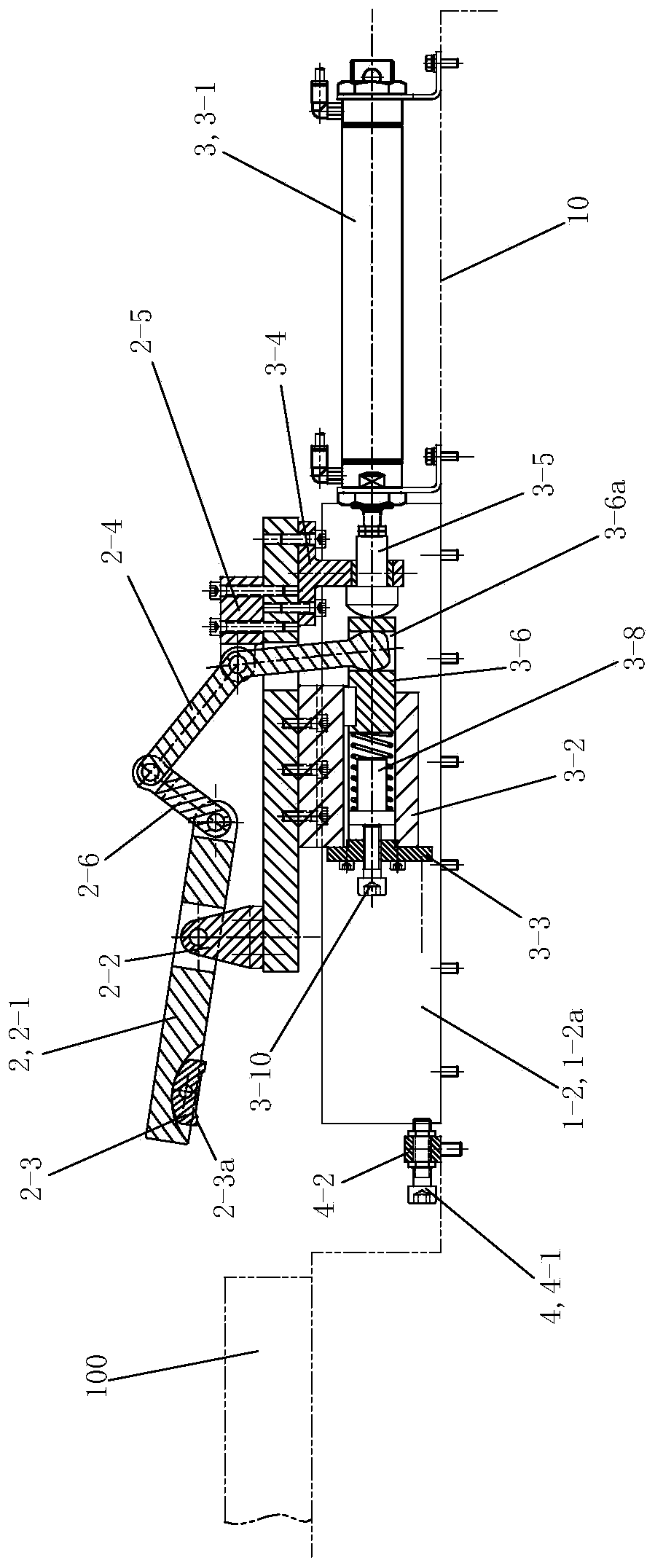
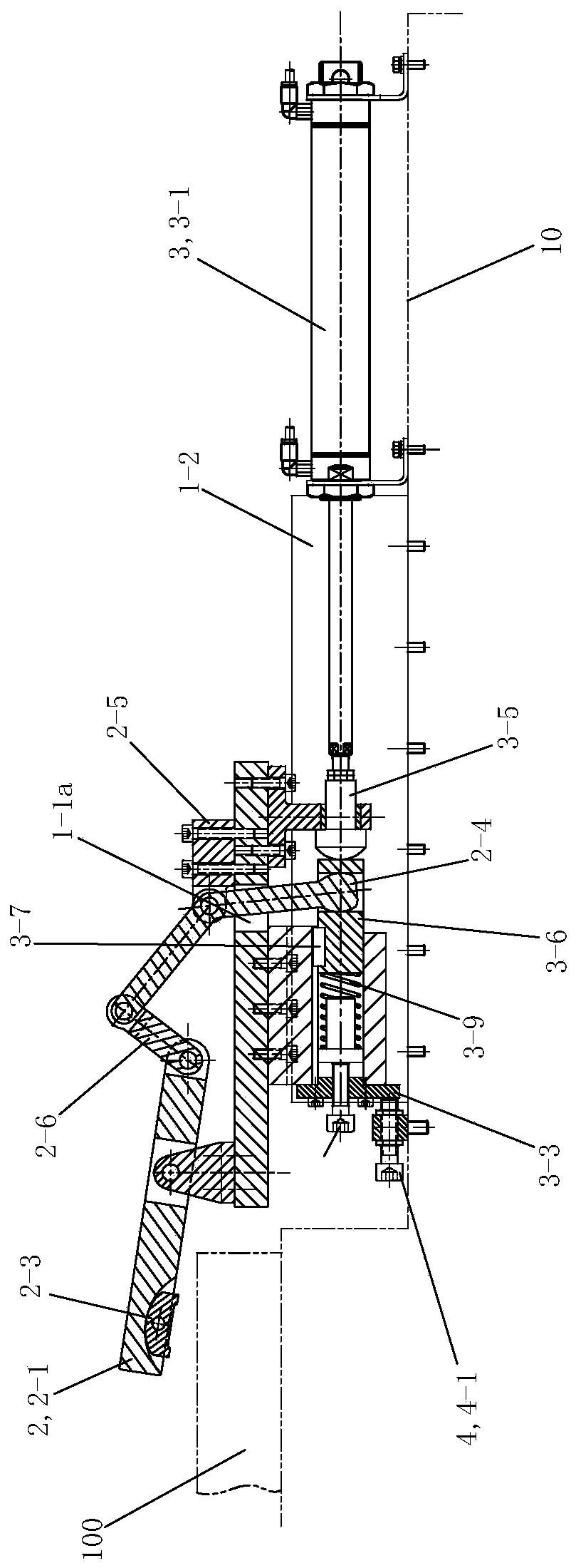
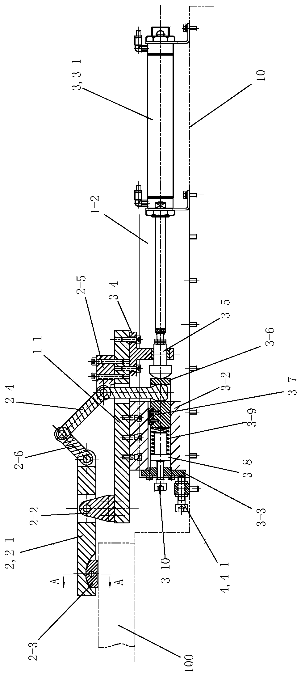
[0040] See Figure 1 to Figure 14 , The workpiece clamping device of the present invention includes a sliding table assembly 1 , a pressing assembly 2 , a driving assembly 3 and a limiting assembly 4 .

[0041] See Figure 1 to Figure 4 , Figure 6 and Figure 7 , The sliding table assembly 1 includes a sliding table 1-1 and a linear guide rail 1-2. The front and back of the slide table 1-1 is provided with a lever hole 1-1a that runs through it up and down. There are two linear guide rails 1-2, and the two linear guide rails 1-2 all adopt four-direction equal-load rolling linear guide rail pairs. The two linear guide rails 1-2 are arranged sequentially from front to back, and are parallel to each other. The guide rails 1-2a of the two linear guide rails 1-2 are fixedly arranged on the corresponding workbenches 10 along the left and right directions. The slide table 1-1 is fixedly arranged on the slide blocks 1-2b of the two linear guide rails 1-2. The slide table 1-1 i...

Embodiment 2)

[0047] See Figure 13 , the rest of this embodiment is the same as that of Embodiment 1, the difference is that: the lower side pressing surface 2-3a of the indenter 2-3 is a rough surface, which is used for pressing the workpiece 100 with a relatively rough surface.

Embodiment 3)

[0049] See Figure 14 , The rest of this embodiment is the same as that of Embodiment 1, the difference is that: the lower pressing surface 2-3a of the indenter 2-3 is an upwardly concave curved surface, which is used for pressing workpieces whose surface is a corresponding curved surface.


PUM


Abstract

The invention discloses a workpiece clamping device. The workpiece clamping device comprises a slide table module, a pressing module, a driving module and a limiting module. The slide table module comprises a slide table and a linear guide rail. The slide table is fixedly arranged on a slide block of the linear guide rail. The travel of the slide table is limited by the limiting module. The pressing module comprises a pressing rod, a pressing rod bracket, a pressing head, a lever, a lever bracket and a connecting rod. The pressing head is arranged at the left part of the lower side of the pressing rod. The pressing rod bracket is fixedly arranged at the middle part of the left part of the upper side of the slide table. The middle part of the pressing rod is rotationally connected to the pressing rod bracket. The lever bracket is fixedly arranged at the middle part of the right part of the upper side of the slide table. The lever is rotationally connected to the lever bracket by the middle part. The right end of the pressing rod is hinged with the lower end of the connecting rod; and the upper end of the connecting rod is hinged with the upper end of the lever. After the slide tableis driven to the limiting place by the driving module, the lever of the pressing module is driven, so that the lever is rotated around a fulcrum of the lever bracket, and the pressing head downwardspresses corresponding workpieces.

Description

technical field [0001] The invention relates to the field of fixtures, in particular to a device for clamping workpieces. Background technique [0002] When disassembling the workpiece, the pressure plate often becomes an obstacle in many occasions, and a special device is required to remove the clamping mechanism, and sometimes it needs to move a large distance (especially on an automatic production line), and the clamping mechanism is installed on the moving slide Work on the top, so that the clamping device can advance and retreat within a large distance (so that there is enough space for other operations at the workpiece installation, such as automatic feeding, automatic positioning, etc.), which is widely used in actual production. Usually the clamping device is installed on the sliding table to work, and two sets of power sources are required. One set is the power source (such as pneumatic, hydraulic or electric) that moves the slide table; the other is the power sour...

Claims


Application Information

Patent Timeline
Patent Type & Authority Patents(China)
IPC IPC(8): B25B11/00B23Q3/08
CPCB23Q3/08B23Q3/082B25B11/00
Inventor 苏沛群王韧邓志辉
Owner CHANGZHOU COLLEGE OF INFORMATION TECH
Why Eureka
Try Eureka