Sludge treatment device for separating slurry and water

A technology for sludge treatment and sludge-water separation, applied in sludge treatment, water/sludge/sewage treatment, chemical instruments and methods, etc., can solve problems such as difficult sludge-water separation and low treatment efficiency

Inactive Publication Date: 2019-04-09
许峰
View PDF9 Cites 2 Cited by
  • Summary
  • Abstract
  • Description
  • Claims
  • Application Information

AI Technical Summary

Problems solved by technology

[0004] Since the water content in the raw sludge can generally reach 99.5%, it is actually difficult to separate the mud and water with the existing centrifugation methods. The water obtained after centrifugation still contains a large amount of sludge, and the treatment efficiency is low.

Method used


Image

  • Sludge treatment device for separating slurry and water
  • Sludge treatment device for separating slurry and water
  • Sludge treatment device for separating slurry and water

Examples


Embodiment 1

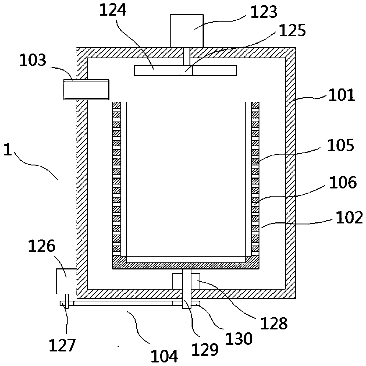
[0031] Sludge treatment devices that facilitate the separation of mud and water, such as Figure 1-Figure 6 As shown, a centrifugal device 1 is included, and the centrifugal device 1 includes an outer cylinder 101 and an inner cylinder 102 arranged in the outer cylinder 101, and the outer cylinder 101 is provided with a mud inlet pipe for transporting raw sludge into the inner cylinder 102 103 and a transmission mechanism 104 for rotating the inner cylinder body 102, wherein the mud inlet pipe 103 is a mud delivery hose, which extends into the inner cylinder body 102 from the side wall of the outer cylinder body 101, and the mud delivery hose needs to be inserted into the inner cylinder body 102 during use. Insert the mouth of the mud inlet pipe 103 on the outer cylinder 101, and allow the end of the mud delivery hose to penetrate into the inner cylinder 102. At this time, the upper extrusion plate 124 is at the highest point, and the upper part performs extrusion.

[0032] Th...

Embodiment 2

[0047] Same as embodiment 1, such as Figure 11 , Figure 12 As shown, the difference is that the mud inlet pipe 103 in this embodiment includes an outer tube 131 fixed on the side wall of the outer cylinder 101 and an inner tube 132 whose end is inserted into the outer tube 131 and can slide axially along the inner wall of the outer tube 131, The inner wall of the outer tube 131 is provided with an annular spring seat 133, the annular spring seat 133 is connected with a spring 134 arranged axially along the outer tube 131, and the end of the spring 134 away from the annular spring seat 133 is connected to the inner tube 132 inserted into the outer tube 131 on the end. The end of the inner tube 132 inserted into the outer tube 131 is fixed with a pressure plate 135. The pressure plate 135 includes an annular plate 136 and a circular plate 138 connected to the middle of the annular plate 136 by two connecting rods 137. The upper surface of the annular plate 136 is provided wit...


PUM


Abstract

The invention relates to a sludge treatment device, and discloses a sludge treatment device for separating slurry and water. The device comprises a centrifuge device, wherein the centrifuge device comprises an outer cylinder and an inner cylinder arranged in the outer cylinder; the outer cylinder is provided with a sludge inlet pipe for feeding raw sludge into the inner cylinder and a transmissionmechanism for rotating the inner cylinder; the inner cylinder comprises a cylinder body, a plurality of water-passing holes are uniformly distributed in the side wall of the cylinder body; a cylindrical frame is arranged in the cylinder body, and comprises an upper ring, a lower ring and four connecting rods for connecting the upper ring and the lower ring; cylindrical gauze sleeves outside the cylindrical frame, and is compressed on the inner wall of the cylinder body through the cylindrical frame. According to the sludge treatment device, gauze is arranged in the cylinder, compared with a filter screen, gauze has the advantage that sludge with more moisture is basically stopped inside the gauze rather than being easily thrown out, and slurry and water separation can be furthest realized.

Description

technical field [0001] The invention relates to a sludge treatment device, in particular to a sludge treatment device which facilitates mud-water separation. Background technique [0002] Sludge treatment is the process of sludge reduction, stabilization and harmless treatment. The higher the degree of wastewater treatment, the more sludge residues are generated that need to be disposed of. For modern sewage treatment plants, the treatment and disposal of sludge has become the most complex and expensive part of the operation of the sewage treatment system. [0003] In the prior art, mud-water separation is generally performed first when sludge is treated, that is, the raw sludge is pumped from the secondary sedimentation tank to another tank through a sludge pump to separate from the supernatant. Before the separation process, the raw sludge is generally concentrated. In the existing technology, mechanical treatment methods such as vacuum filtration and centrifugation are ...

Claims


Application Information

Patent Timeline
Patent Type & Authority Applications(China)
IPC IPC(8): C02F11/122C02F11/127C02F11/121
CPCC02F11/121C02F11/122C02F11/127
Inventor 许峰
Owner 许峰
Why Eureka
Try Eureka