Round head button hole sewing machine

A sewing machine, buttonhole technology, applied in the direction of sewing machine components, program-controlled sewing machines, sewing equipment, etc.

Inactive Publication Date: 2005-08-03
DURKOPP ADLER AG
View PDF4 Cites 2 Cited by
  • Summary
  • Abstract
  • Description
  • Claims
  • Application Information

AI Technical Summary

Problems solved by technology

In doing so, problems arise due to the fact that the compres

Method used


Image

  • Round head button hole sewing machine
  • Round head button hole sewing machine
  • Round head button hole sewing machine

Examples


Embodiment Construction

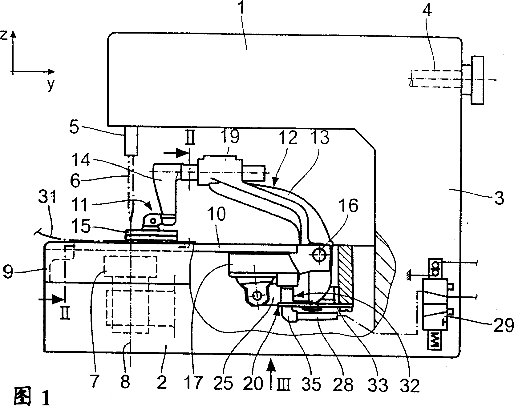
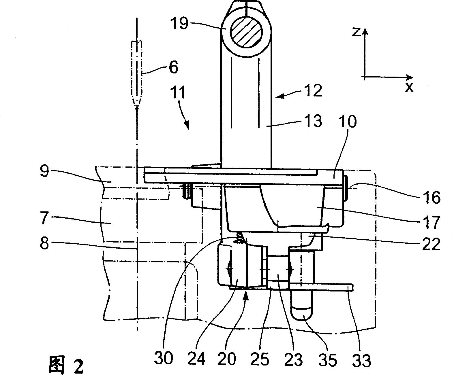
[0023] As shown in FIG. 1 , a buttonhole sewing machine with a round head is designed in a C shape, which has a top arm 1 , a shell-shaped bottom base plate 2 and an approximately vertical column 3 connecting the top arm and the bottom base plate. An arm shaft 4 is arranged in the arm 1 in a conventional manner; it can be driven by a drive motor (not shown). The drive for the needle bar 5 , which is movable vertically in the z direction and has a needle 6 , as well as its reciprocating / pivoting drive originate in the usual manner from the arm shaft 4 . Below the needle bar 5 and the needle 6 there is arranged in the base plate 2 a wire hook support 7 ; it can be driven to rotate about a vertical axis 8 . The drive for the wire hook support 7 originates from the arm shaft 4 in a conventional manner.

[0024] An x-y worktable 9 is arranged on the base plate 2; the worktable is a cross slide that can move along two horizontal coordinate directions, namely the x direction and the...


PUM


Abstract

The present invention designs a round-head buttonhole sewing machine, which includes an x-y workbench (9) on which a sewing material clamp (11) mounted for movement in the x direction is arranged. The sewing clamp (11) is actuated by a pneumatically actuated piston-cylinder drive (20) mounted on the sewing clamp (11) and connected to a compressed air hose (28). The compressed air hose (28) is detachably connected to the piston-cylinder drive (20) by means of a hose connection (32).

Description

technical field [0001] The invention relates to a buttonhole sewing machine with a round head, which comprises a base plate; a needle which can be driven in a z direction by means of an arm shaft; a thread hook support which is arranged in the base plate below the needle; An x-y worktable on the substrate and movable along an x-direction and a y-direction; at least one sewing material clamp mounted on the x-y worktable to move along the x-direction and movable by means of a sliding drive device; the sewing material clamp a lower clamping plate detachable from the x-y table upwards in the z-direction and connectable to the x-y table from above in the z-direction, the sewing clamp also has an upper clamping plate hinged to the lower clamping plate; a clamping drive, which is mounted on the lower clamping plate and consists of a pneumatically operable piston-cylinder drive for actuating the upper clamping plate; Compressed air hose for compressed air supply to the clamp drive. ...

Claims


Application Information

Patent Timeline
IPC IPC(8): D05B29/12D05B3/06D05B3/08D05B19/12D05B29/00
CPCD05B3/08D05D2207/02B65F1/1426B65F1/1473B65F1/0053B65F1/1646B65F1/1615B65F2210/138
Inventor H·博尔H·弗兰辛T·约尔旦
Owner DURKOPP ADLER AG
Why Eureka
Try Eureka