

Imaging device of large geotechnical centrifuge
A geotechnical centrifuge and imaging device technology, which is applied to the camera body, camera, image communication, etc., can solve the problem that the shooting position and focal length, the exposure time cannot be adjusted accurately, and the force of the geotechnical model cannot be accurately reflected. Long distance and other problems, to achieve the effects of easy implementation, improved clarity, and long service life
- Summary
- Abstract
- Description
- Claims
- Application Information
AI Technical Summary
Problems solved by technology
Method used
Image

Examples
Embodiment
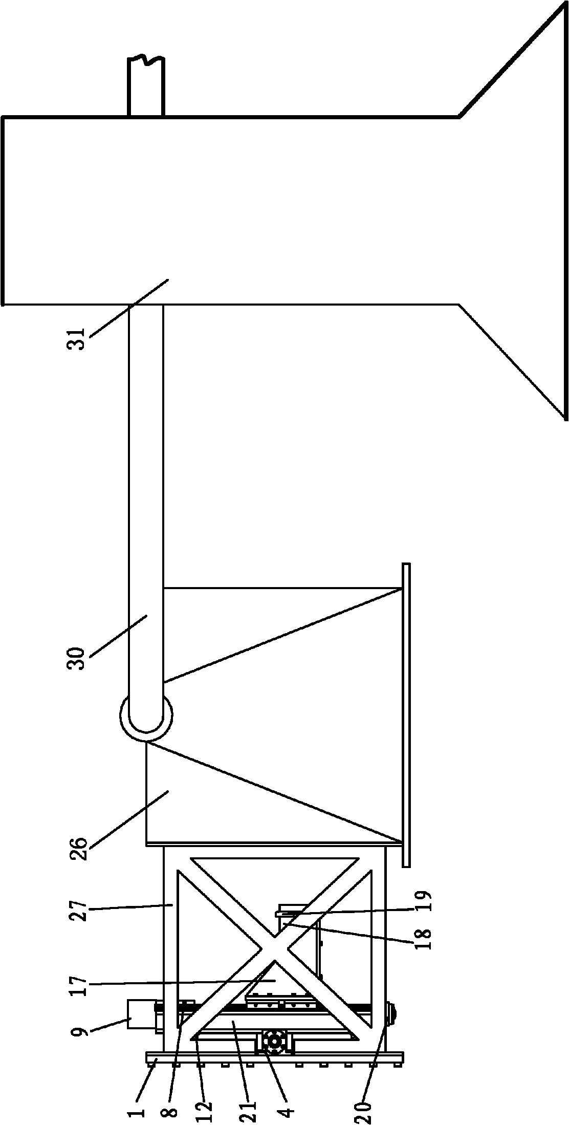
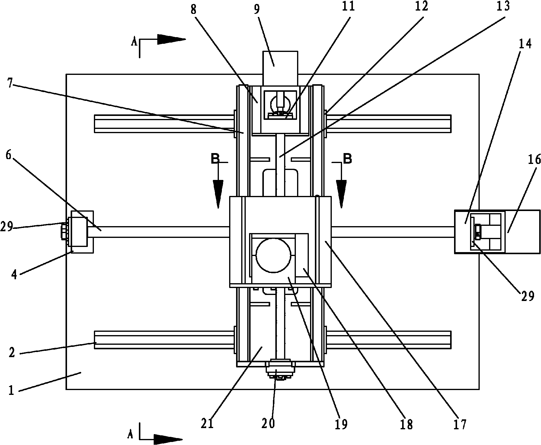
[0025] Figure 1-4 Shown, a kind of embodiment of the present invention is, the imaging device of a kind of large-scale geotechnical centrifuge, and its composition is: the outside of the model case 26 of centrifuge is fixed with camera support 27, on the outer frame of camera support 27 A two-dimensional mobile device that can move horizontally and vertically is vertically fixed, and the camera 18 is fixed on the two-dimensional mobile device, and the lens direction of the camera 18 faces the model box 26. The two-dimensional mobile device and the camera 18 are all connected with data control and processing. The device is electrically connected.
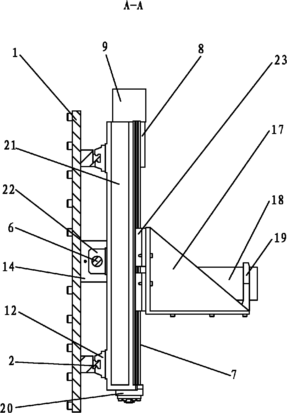
[0026] The specific composition of the two-dimensional mobile device in this example is:
[0027] Camera 18 is fixed on the camera support 17, and the lens of camera 18 fits in the hole of grating seat 19 on the camera support 17, and the back of camera support 17 (that is, the side of camera support away from camera lens or centri...
PUM
 Abstract
Description
Claims
Application Information