Beam halo treatment nonlinear magnet for accelerator

A non-linear, accelerator technology, applied in the direction of accelerators, electrical components, etc., can solve the problem of activation that is difficult to solve fundamentally, and achieve the effect of avoiding adverse effects

Inactive Publication Date: 2015-06-17
CHINA INSTITUTE OF ATOMIC ENERGY
View PDF5 Cites 3 Cited by
  • Summary
  • Abstract
  • Description
  • Claims
  • Application Information

AI Technical Summary

Problems solved by technology

[0003] At present, the treatment of beam halo at home and abroad is the method of collimator, and the problem of activation is difficult to solve fundamentally.

Method used


Image

  • Beam halo treatment nonlinear magnet for accelerator
  • Beam halo treatment nonlinear magnet for accelerator
  • Beam halo treatment nonlinear magnet for accelerator

Examples


Embodiment Construction

[0012] The present invention will be described in detail below in conjunction with the accompanying drawings and embodiments.

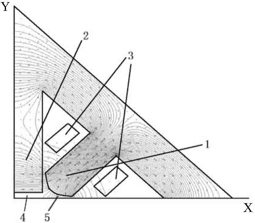
[0013] The present invention is an improvement on the basis of the quadrupole magnet adopted by the accelerator. The original quadrupole magnet includes four magnetic poles 1 arranged oppositely in pairs, and each magnetic pole is provided with an excitation wire package 3 and is fed with an excitation current. like figure 1 as shown, figure 1 The drawing in is a quarter of the whole magnet, and the whole picture is symmetrical about the X coordinate axis and the Y coordinate axis. In the present invention, a pair of shielding magnetic poles 2 are added in the middle of the four magnetic poles, and the pole head is a plane, so that the magnetic field generated by it is a zero field area 4 . The pole head surface of the original quadrupole magnet pole 1 is a hyperboloid, such as the curved surface formed by the stretching of the (x-a)*y=b curve along...


PUM


Abstract

The invention belongs to accelerator design techniques, and particularly relates to a beam halo treatment nonlinear magnet for an accelerator. The beam halo treatment nonlinear magnet for the accelerator comprises four magnetic poles, every two magnetic poles are oppositely arranged, and an excitation coil is arranged outside each magnetic pole, wherein a pair of shaded poles are arranged in the middle of the four magnetic poles, the magnetic pole head of each shaded pole is a plane, magnetic fields generated by the plane magnetic pole heads are null fields, and the magnetic fields generated by the magnetic pole heads of the four magnetic poles are linear focusing areas or non-linear focusing areas. The beam halo treatment nonlinear magnet for the accelerator can generate a wider range of null field and focusing field strength, so that the current beam halo treatment problem can be overcome, low-density particles at the edges are focused and overlaid on the high-density particles of the center, and the adverse impact of beam halo particles is avoided.

Description

technical field [0001] The invention belongs to the accelerator design technology, in particular to a beam halo processing nonlinear magnet for an accelerator. Background technique [0002] The particle distribution of the transverse section (beam spot) of the beam generated by the accelerator is generally Gaussian distribution, that is, the distribution of particles bombarded on the target is not uniform. Gaussian distribution of the beam spot will have a small area of ​​high-density beam nucleus and a large area of ​​low-density beam halo around the beam nucleus. For particles with medium and low energies, beam halo particles can be directly blocked by a collimator, but after acceleration and transmission, new beam halo particles will be generated. For high-energy particles, after the beam halo particles bombard the collimator and beam pipe, a large radiation dose will be generated, resulting in the activation of matter. Therefore, accelerator beam halo handling is a ver...

Claims


Application Information

Patent Timeline
Patent Type & Authority Applications(China)
IPC IPC(8): H05H7/04
Inventor 李金海任秀艳曾自强
Owner CHINA INSTITUTE OF ATOMIC ENERGY
Why Eureka
Try Eureka