Flow control ejection system for aircraft model low-speed wind tunnel test

A wind tunnel experiment and flow control technology, which is applied to the testing of machines/structural components, instruments, and measuring devices, can solve problems such as limited intake flow, affecting experimental results, and congestion at the exhaust outlet of the main intake pipe. To achieve the effect of increasing the intake flow and improving the authenticity

Active Publication Date: 2019-04-09
XIAN AIRCRAFT DESIGN INST OF AVIATION IND OF CHINA
View PDF24 Cites 5 Cited by
  • Summary
  • Abstract
  • Description
  • Claims
  • Application Information

AI Technical Summary

Problems solved by technology

[0004] The technical problem solved by the present invention is to provide a flow control injection system for the low-speed wind tunnel experiment of the aircraft model, which is used to solve the problem that the existing injection system is easy to cause congestion at the exhaust outlet of the main air intake pipe, and the air intake flow is limited, which affects The problem with experimental results

Method used


Image

  • Flow control ejection system for aircraft model low-speed wind tunnel test

Examples


Embodiment Construction

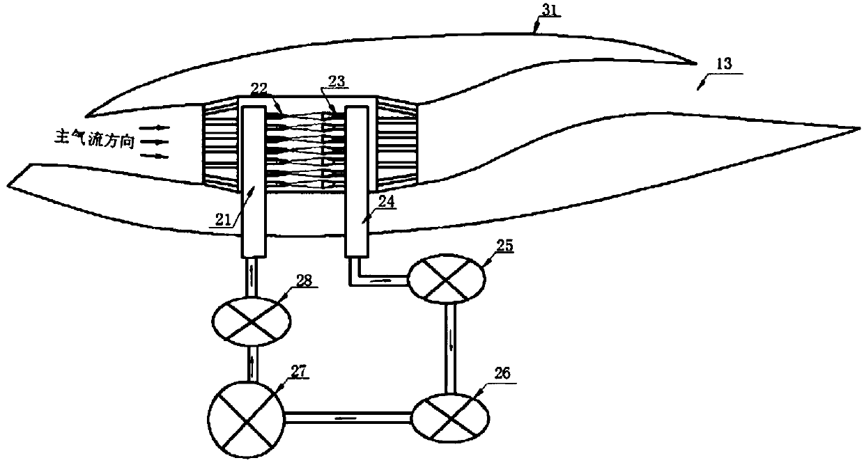
[0016] A flow control injection system for aircraft model low-speed wind tunnel experiments, comprising a body 31, the inside of the body 31 is provided with a main air intake duct 13, and also includes a high-pressure nozzle support 21, a high-pressure air intake nozzle support 24, a recovery Supercharging device 25, air intake controller 28, one-way valve 26 and high-pressure gas tank 27, described main air intake pipe 13 is provided with a cylindrical cavity inside, described high-pressure air intake nozzle support 24 and high-pressure nozzle The support 21 is arranged on both sides inside the cylindrical cavity, the bottom of the high-pressure air inlet nozzle support 24 passes through the body 31 and communicates with the recovery booster 25, and the high-pressure nozzle support 21 passes through the body 31 and connects with the inlet The air controller 28 communicates, the air intake controller 28 communicates with the high-pressure gas tank 27, the one-way valve 26 comm...


PUM


Abstract

The invention discloses a flow control ejection system for an aircraft model low-speed wind tunnel test. When the aircraft model low-speed wind tunnel test is carried out, a high-pressure air intake nozzle recovers most of the high-pressure airflow sprayed by a high-pressure spray nozzle, the high-pressure airflow enters a recovery pressurization device for pressurization and returns to a high-pressure air tank through a one-way valve, and the main airflow and a small part of the high-pressure airflow are discharged through an outlet of a main air intake pipeline. Since most of the high-pressure airflow is recovered and does not flow through the outlet of the main air intake pipeline, the congestion of the outlet of the main air intake pipeline cannot be caused, the air intake flow of themain air intake pipeline is increased, the simulated flow of the main air intake pipeline in the aircraft model low-speed wind tunnel test can be increased to reach 100% of the design flow, and thus the real working condition can be more closely approximated, and the authenticity of the test can be improved.

Description

technical field [0001] The invention relates to the technical field of aircraft model low-speed wind tunnel experiments, in particular to a flow control injection system for aircraft model low-speed wind tunnel experiments. Background technique [0002] In the low-speed wind tunnel experiment of the aircraft model, in order to simulate the influence of the intake effect on the lift and drag of the aircraft, an ejector system is generally designed inside the low-speed wind tunnel model of the aircraft to simulate the inlet flow of the air inlet. [0003] In the existing injection system, after the injection high-pressure gas enters the main airflow, it will be mixed with the main airflow, and will be discharged from the exhaust outlet of the main air intake pipe together. As the pressure of the injection high-pressure air increases, the main air intake pipe will exhaust The outlet pressure increases rapidly and quickly reaches a congested state. When the ejection capacity of ...

Claims


Application Information

Patent Timeline
Patent Type & Authority Applications(China)
IPC IPC(8): G01M9/06
CPCG01M9/065
Inventor 孔德英艾俊强王家启高翔
Owner XIAN AIRCRAFT DESIGN INST OF AVIATION IND OF CHINA
Why Eureka
Try Eureka