Cable detection method, device and electronic device

A detection method and cable technology, applied in the detection field, can solve problems such as the inability to achieve quantitative detection of WTB cables, and achieve the effects of accurate and accurate detection results, elimination of signal attenuation, and comprehensive detection results.

Active Publication Date: 2021-03-23
上海仁童电子科技有限公司
View PDF6 Cites 0 Cited by
  • Summary
  • Abstract
  • Description
  • Claims
  • Application Information

AI Technical Summary

Problems solved by technology

[0005] In view of the above problems, the present application provides a cable detection method, device and electronic equipment, which solves the technical problem that the existing VNA measurement method cannot realize the quantitative detection of WTB cables

Method used


Image

  • Cable detection method, device and electronic device
  • Cable detection method, device and electronic device
  • Cable detection method, device and electronic device

Examples


Embodiment Construction

[0064] In order to make the above purpose, features and advantages of the present application more obvious and understandable, the technical solutions in the embodiments of the present application will be clearly and completely described below in conjunction with the drawings in the embodiments of the present application. Obviously, the described implementation Examples are only some of the embodiments of the present application, but not all of them. Based on the embodiments in this application, all other embodiments obtained by persons of ordinary skill in the art without making creative efforts belong to the scope of protection of this application.

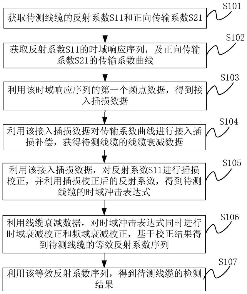
[0065] refer to figure 1 , is a schematic flow chart of a cable detection method provided in the embodiment of the present application. The method can be executed by a cable tester or other equipment with data processing capabilities. limited, such as figure 1 As shown, the method may include but is not limited to the followin...


PUM


Abstract

The invention provides a cable detection method and device and electronic equipment. According to the cable detection method and device and the electronic equipment, access insertion loss data causedby a connection part between detection equipment and a to-be-detected cable and access insertion loss data caused by the to-be-detected cable can be directly obtained by utilizing a measured reflection coefficient and a measured forward transmission coefficient without adding extra hardware consumption, so that the access insertion data can be utilized to carry out insertion loss correction on thereflection coefficient and get rid of access energy loss in the reflection coefficient so as to obtain a time domain impact expression, of the reflection coefficient, generated by personal factors ofthe to-be-detected cable; in such a way, time domain attenuation correction and frequency domain attenuation correction can be carried out on the time domain impact expression at the same tine by utilizing obtained cable attenuation data so as to obtain an equivalent reflection coefficient sequence of the to-be-detected cable; and the equivalent reflection coefficient sequence is capable of intuitionally reflecting fault degrees of a near end and a far end of the to-be-detected cable and quantitatively describing the quality of the to-be-detected cable so as to obtain a correct and comprehensive detection result.

Description

technical field [0001] The present application relates to the technical field of detection, and more specifically relates to a cable detection method, device and electronic equipment. Background technique [0002] In cable fault detection, the current cable tester usually uses VNA (Vector Network Analyzer, vector network analysis) method to detect the quality of the cable, that is, using the inverse Fourier transform method to observe the change of the signal strength in the time domain, so that Determine cable quality or locate faults. [0003] However, for a longer cable, the signal tends to attenuate with the length of the cable. For example, for a WTB (Wire TrainBus, twisted train bus) cable, the bandwidth design is low and the high frequency attenuation is severe. If the VNA method is used to detect a long WTB cable, the time-domain image of the "reflection coefficient" used to measure the quality of the cable will be attenuated, and the attenuation is caused by the le...

Claims


Application Information

Patent Timeline
Patent Type & Authority Patents(China)
IPC IPC(8): G01R31/08
CPCG01R31/083G01R31/088
Inventor 易国锴
Owner 上海仁童电子科技有限公司
Why Eureka
Try Eureka