An Atomic Magnetic Microscopy Method Based on Cavity Resonance and Magnetic Concentration Structures

A magnetic aggregation, atomic technology, applied in the size/direction of the magnetic field, measuring magnetic variables, electromagnetism and other directions, can solve the problems of reducing the magnetic field sensitivity, sample magnetic field attenuation, etc., to achieve shortened settling time, enhanced signal contrast, high sensitivity Effect

Inactive Publication Date: 2019-11-08
BEIHANG UNIV
View PDF1 Cites 0 Cited by
  • Summary
  • Abstract
  • Description
  • Claims
  • Application Information

AI Technical Summary

Problems solved by technology

However, in the follow-up work, it was found that there are two problems in short-pulse magnetic microscopy: 1. In short-pulse magnetic microscopy, the polarizability establishment time accounts for a large proportion of the pulse period; 2. Due to the There is a certain thickness of the wall, resulting in a certain distance between the sample to be tested and the sensitive atoms, which in turn attenuates the magnetic field of the sample and reduces the sensitivity of the magnetic field

Method used


Image

  • An Atomic Magnetic Microscopy Method Based on Cavity Resonance and Magnetic Concentration Structures
  • An Atomic Magnetic Microscopy Method Based on Cavity Resonance and Magnetic Concentration Structures
  • An Atomic Magnetic Microscopy Method Based on Cavity Resonance and Magnetic Concentration Structures

Examples


Embodiment Construction

[0032] The present invention will be further described below in conjunction with the accompanying drawings and specific embodiments.

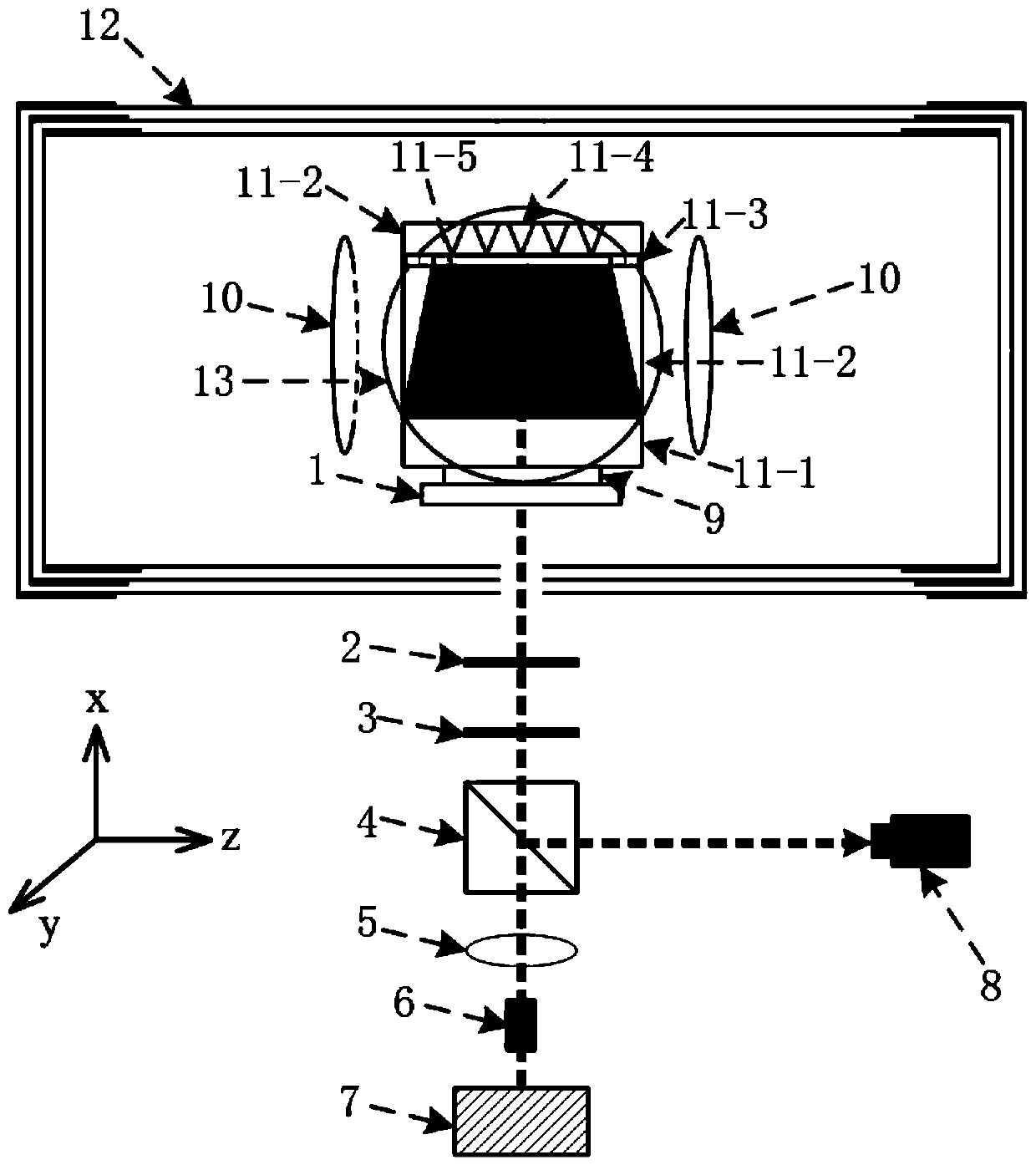
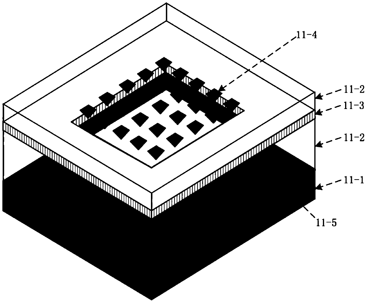
[0033] Such as figure 1 and figure 2 As shown, an atomic magnetic microscopy method based on cavity resonance and magnetic concentration structure, the device used in this method includes a short pulse laser 7, an optical isolator 6, a collimator lens 5, a broadband beam splitter prism 4, and a Glan-Taylor prism 3 , a quarter-wave plate 2, a concave mirror 1, an annular piezoelectric ceramic 9, a magnetic shield barrel 12, a magnetically concentrated atom gas chamber 11, a z-direction magnetic field coil 10, a y-direction magnetic field coil 13 and a CCD detector 8, using A short-pulse laser 7 with a wavelength of 894.5nm is used for pumping and detecting alkali metal cesium atoms at the same time. The pulse power of the laser is 100W; the pulsed laser passes through the optical isolator 6, collimator lens 5, broadband beam splitter 4, and Gl...


PUM


Abstract

The invention discloses an atom magnetic microscopy method based on cavity resonance and magnetic aggregation structure, a cavity resonance short pulse measurement method and an MEMS magnetic aggregation structure are utilized to respectively improve spatial resolution and magnetic field sensitivity of an atom magnetic micrioscopy magnetic field, the cavity resonance short pulse measurement method is to put an atomic gas chamber in a resonant cavity formed by pulse pumping light, the amplification of the pumping light is performed through the resonant cavity, and the polarization rate setting time of the pulse pumping light is shortened. In addition, in the method, non-linear amplification is performed on the space variation of the magnetic filed through magnetic filed variation-deturning- polarization rate reduction-deturning mechanism, so that the contrast ratio of the signal is greatly increased. MEMS magnetic aggregation structure is to utilize MEMS technology to prepare an atom side wall with a magnetic aggregation structure, and a required atomic gas chamber is prepared through a gas injection and bonding technology in an anaerobic box. The purpose of the invention is to guide a magnetic field generated by a to-be-detected sample on the surface of the atomic gas chamber in the gas chamber, and the amplification of the magnetic field can be realized through the magnetic aggregation structure.

Description

technical field [0001] The invention relates to an atomic magnetic microscopy technology based on cavity resonance and a magnetic aggregation structure, and belongs to the technical field of atomic magnetometers. Background technique [0002] Magnetic microscopy is the delicate measurement of magnetic field distributions. Through magnetic microscopic observation, the growth and development process of magnetic proteins can be characterized, and the weak magnetic distribution measurement of materials and non-destructive diagnosis of integrated circuits can also be carried out. [0003] In magnetic microscopic measurement, its main technical indicators are spatial resolution and magnetic field sensitivity. Common magnetic microscopy techniques include nitrogen vacancy color center (NV color center), Bose-Einstein condensate (BEC), superconducting quantum interference technique (SQUID) and atomic magnetometer technique (AM). The NV color center magnetic microscope has a high s...

Claims


Application Information

Patent Timeline
Patent Type & Authority Patents(China)
IPC IPC(8): G01R33/028
CPCG01R33/0286
Inventor 董海峰高阳王笑菲尹凌霄
Owner BEIHANG UNIV
Why Eureka
Try Eureka