An electrochemical system and a method for changing the response mode of a plasmon sensor

An electrochemical and electrode technology, applied in the field of materials, to achieve high signal contrast and achieve reversible switching effects

Active Publication Date: 2021-09-24
NANJING UNIV
View PDF0 Cites 0 Cited by
  • Summary
  • Abstract
  • Description
  • Claims
  • Application Information

AI Technical Summary

Problems solved by technology

However, the electrical control of magnetic metamaterials is extremely challenging due to discontinuous structures (e.g., split resonant rings, coupled nanoparticles, multiple stacked rods), but researchers are eager to achieve in situ Manipulation of local structure to tune magnetic plasmon resonance (MPR) and apparent magnetic field enhancement

Method used


Image

  • An electrochemical system and a method for changing the response mode of a plasmon sensor
  • An electrochemical system and a method for changing the response mode of a plasmon sensor
  • An electrochemical system and a method for changing the response mode of a plasmon sensor

Examples


Embodiment 1

[0098] In this embodiment, a magnetic plasmon sensor is prepared.

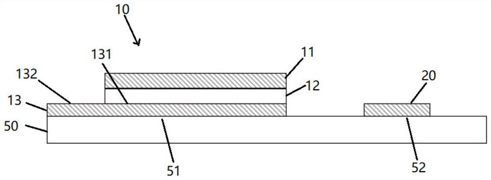
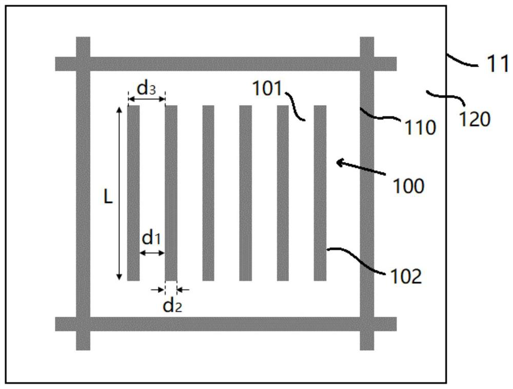
[0099] figure 1 A side view of the plasmon sensor of Example 1 is shown. figure 2 A top view of the metal upper layer of the plasmonic sensor of Example 1 is shown. image 3 An electrochemical system including the plasmonic sensor is shown.

[0100] Such as figure 1 and 2 As shown, the preparation method of the plasmonic sensor 10 is as follows:

[0101] (1) Provide a quartz plate 50 with a thickness of 1mm, divide the first area 51 and the second area 52 on the quartz plate 50, the first area 51 is used to set the plasmon sensor 10, and the second area 52 is subsequently used for configuring the second electrode when assembling the electrochemical system;

[0102] (2) Deposit a metal substrate 13 (material: Ag) with a thickness of 100 nm on the first region 51 by using a physical vapor deposition method;

[0103] (3) adopt the physical vapor deposition method, divide the 3rd region 131 and the 4th reg...

Embodiment 2

[0114] In this example, an electrochemical system containing a plasmon sensor was prepared.

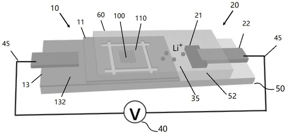
[0115] image 3 A schematic diagram of the electrochemical system of Example 2 is shown.

[0116] As shown in the figure, the electrochemical system includes the component I of Embodiment 1, that is, a quartz plate 50 and a plasmon sensor 10 disposed thereon. The plasmonic sensor 10 serves here as the first electrode of the electrochemical system.

[0117] On this basis, the electrochemical system further includes a second electrode 20 . The second electrode 20 includes an active material 21 (lithium iron phosphate LiFePO 4 ), the active material 21 is disposed at the second region 52 of the quartz wafer 50 . The second electrode 20 also includes a tab 22 connected to the active material 21 .

[0118] On this basis, the electrochemical system further includes a power supply 40 and a wire 45, the third region 132 of the metal substrate 13 of the plasmon resonance sensor 10 is conn...

Embodiment 3

[0136] The difference between embodiment 3 and embodiment 2 lies in the location of the electrolyte. Figure 6 A schematic diagram of the electrochemical system of this example is shown.

[0137] In this embodiment, the opposite side of the quartz plate 50 is covered with a glass plate 60, the gaps around the glass plate 60 and the quartz plate 50 are sealed with epoxy resin, and the island-shaped region 110 and the active material 21 are sandwiched between the two. The epoxy resin seals the gaps around the glass plate 60 and the quartz plate 50 to form a cavity, and the island region 110 and the active material 21 are sealed in the cavity. The third region 132 of the upper metal layer 13 and part of the tabs 22 are not sealed in the cavity, and are subsequently used to connect to the power source 40 through the wire 45 .

[0138] A small hole is reserved for injecting electrolyte when sealing. After the epoxy resin glue is dry and stable, the sample is transferred to an ine...


PUM

PropertyMeasurementUnit
thicknessaaaaaaaaaa
thicknessaaaaaaaaaa
thicknessaaaaaaaaaa

Abstract

The invention relates to an electrochemical system and a method for changing the response mode of a plasmon sensor. The electrochemical system includes a first electrode, a second electrode and an electrolyte, and the first electrode and the second electrode are respectively in contact with the electrolyte; wherein, the first electrode includes: a metal substrate; and a plurality of electrodes arranged on the metal substrate Nano element; wherein each nano element includes a dielectric lower layer and a metal upper layer, and the dielectric lower layer is located between the metal upper layer and the metal substrate; wherein the second electrode includes a conductor; wherein the electrolyte contains lithium ions.

Description

technical field [0001] The invention relates to the field of materials, in particular to an electrochemical system and a method for changing the response mode of a plasmon sensor. Background technique [0002] Due to the ability to dynamically switch plasmonic responses, dynamic plasmonic micro-nanostructures have aroused great research interest in the fields of physics, chemistry, and materials science. [0003] Dynamic plasmons can dynamically control the optical response through structural transformation or material phase transition, thus stimulating a huge research boom in the fields of nanophotonics and metamaterials. Due to the inherent self-established electric field function, flexible modulation and compatibility, the electrical regulation of metal structures is the most important among various dynamic control methods, and is widely used to control the electronic resonance in topologically continuous metal structures, This is a new electrical control path in additio...

Claims


Application Information

Patent Timeline
Patent Type & Authority Patents(China)
IPC IPC(8): G01N27/26H01M10/0525B82Y40/00
CPCB82Y40/00G01N27/26H01M10/0525Y02E60/10
Inventor 朱嘉周林金艳梁洁
Owner NANJING UNIV
Why Eureka
Try Eureka