
A kind of welding machine head and welding method thereof

A technology for welding machine heads and machine heads, which is applied in the field of machinery, can solve the problems of poor flatness and aesthetics, no effective shock absorption, residues and bumps in welding parts, etc., to achieve scientific and reasonable structure, safe and convenient use, and guarantee stable effect

Active Publication Date: 2020-06-30
固安县朔程燃气有限公司
View PDF8 Cites 0 Cited by
  • Summary
  • Abstract
  • Description
  • Claims
  • Application Information

AI Technical Summary

Problems solved by technology

[0003] The present invention provides a welding head and its welding method, which can effectively solve the above-mentioned background technology. The welding head currently on the market has no auxiliary function during installation, and the user needs to hold the welding head with one hand and turn the bolt with the other hand. Fixing the nuts is not convenient for workers to quickly operate. At the same time, there is no effective shock absorption function after installation, and it is easy to cause the shaking of the welding head during welding and it is difficult to eliminate. There are many residues and bumps in the welding part, and the flatness and appearance are poor, which needs to be dealt with in the later stage

Method used


Image

  • A kind of welding machine head and welding method thereof
  • A kind of welding machine head and welding method thereof
  • A kind of welding machine head and welding method thereof

Examples


Embodiment 1

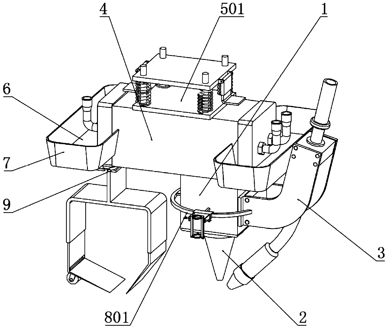
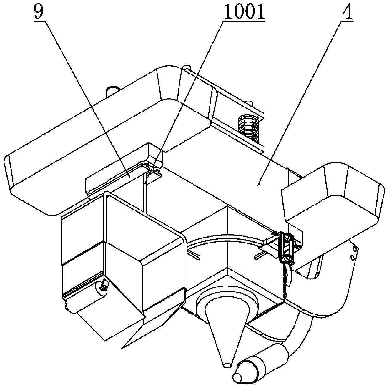
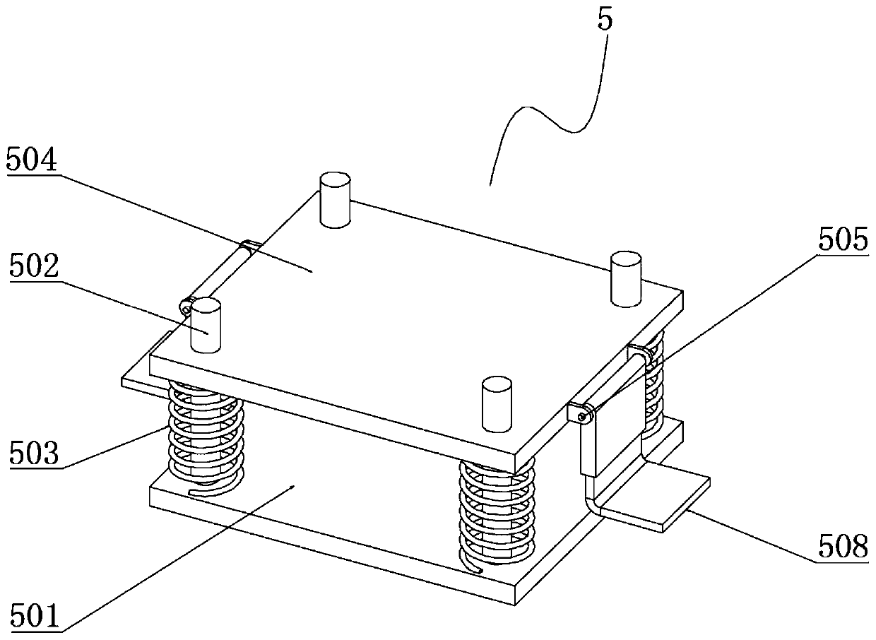
[0043] Example 1: Such as Figure 1-6 As shown, the present invention provides a technical solution, a welding head and a welding method thereof, including a condenser head 1, a protective cover 2 is installed at the bottom end of the condenser head 1, and a side surface of the condenser head 1 is installed There is a mounting frame 3, a water cooler 4 is installed on the top of the condenser head 1, and a connecting mechanism 5 is installed on the top of the water cooler 4. The connecting mechanism 5 includes a fixed plate 501, a locking screw 502, a shock-absorbing spring 503, and a shock-absorbing pad 504 , Fixed post 505, connecting sleeve 506, clamping spring 507, clamping bent plate 508;

[0044] A fixed plate 501 is welded to the middle of the top of the water cooler 4, and a locking screw 502 is welded at each corner of the top of the fixed plate 501. A shock-absorbing spring 503 is installed at the top of the fixed plate 501 corresponding to the outside of the locking sc...


PUM


Abstract

The invention discloses a welding head and a welding method thereof. The welding head comprises a condensation machine head, a water cooler is arranged on the top end of the condensation machine head,a connecting mechanism is arranged on the top end of the water cooler, a damping cushion block is arranged on the top end of a damping spring, a clamping spring is arranged in a connecting casing pipe, and a clamping bending plate is arranged on the bottom end of the clamping spring. The welding head is scientific and reasonable in structure and safe and convenient to use, a mounting mechanism isarranged, through the effect of the clamping bending plate and the clamping spring, the dual hands of a user can be liberated during mounting, the user can more rapidly and stably fix the welding head, the problem that when an existing welding head is mounted, the user needs to hold the welding head by one hand, the other hand rotates a bolt and nut for fixing, and rapid operation by a worker isnot facilitated can be solved, meanwhile, the mounting mechanism is internally provided with the damping cushion block and the damping spring, shaking of the welding head during welding can be effectively reduced, and machining stability of the welding mechanism is ensured.

Description

Technical field [0001] The present invention relates to the technical field of machinery, in particular to a welding head and a welding method thereof. Background technique [0002] Welding, also known as welding, welding, is a manufacturing process and technology for joining metals or other thermoplastic materials such as plastics by heating, high temperature or high pressure. There are many energy sources for modern welding, including gas flame, electric arc, Laser, electron beam, friction and ultrasonic, but the welding heads currently on the market do not have auxiliary functions during installation. Users need to hold the welding head with one hand and turn the bolts and nuts with the other hand to fix it, which is not convenient for workers to operate quickly. At the same time, there is no effective shock absorption function after installation, and the welding head is prone to be difficult to eliminate during welding. At the same time, the existing welding head is difficult...

Claims


Application Information

Patent Timeline
Patent Type & Authority Patents(China)
IPC IPC(8): B23K26/21B23K26/70B23K26/142B23K26/08
CPCB23K26/0869B23K26/142B23K26/21B23K26/702
Inventor 李国洪孙东辉王喜斌王宏宇李津宇叶昊杨超张淼宫旭泽王赛云王冠宇裴梦琴赵建鹏
Owner 固安县朔程燃气有限公司
Learn More