Anti-rolling device for automobile
An anti-roll and automobile technology, which is applied in the direction of body, tractor, motor vehicle, etc., can solve the problems of complex structure, high production cost, poor stability and riding comfort of anti-roll device.
- Summary
- Abstract
- Description
- Claims
- Application Information
AI Technical Summary
Problems solved by technology
Method used
Image
Examples
Embodiment 1
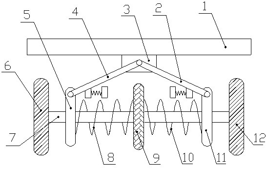
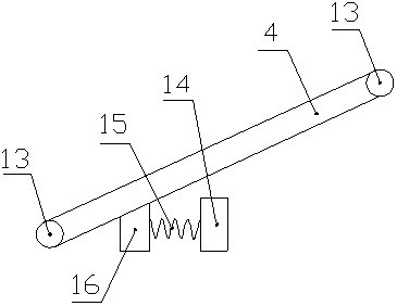
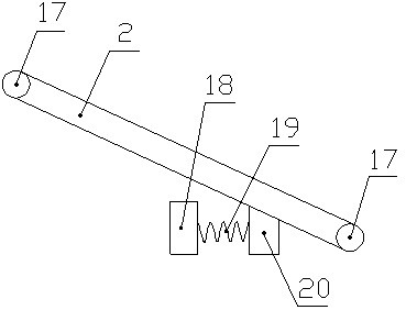
[0018] Such as Figure 1-6 Shown, a kind of automobile anti-roll device, it comprises chassis 1, left wheel 6 and right wheel 12, is connected with axle 7 between described left wheel 6 and right wheel 12, described axle 7 left side and the right side are respectively connected with a left block 5 and a right block 11 through bearings, the middle part of the axle 7 is slidably connected with a slide block 9, and the left end of the slide block 9 is fixedly connected with a spring A8, and the spring A8 The other end of the other end is fixedly connected with the right end of the left block 5, the right end of the slider 9 is fixedly connected with a spring B10, the other end of the spring B10 is fixedly connected with the left end of the right block 11, the spring A8 and The springs B10 are all sleeved on the outside of the axle 7, the middle part of the lower end of the chassis 1 is fixedly connected with the fixed block 3, and the middle part of the fixed block 3 is connected...
Embodiment 2
[0021] Such as Figure 1-6Shown, a kind of automobile anti-roll device, it comprises chassis 1, left wheel 6 and right wheel 12, is connected with axle 7 between described left wheel 6 and right wheel 12, described axle 7 left side and the right side are respectively connected with a left block 5 and a right block 11 through bearings, the middle part of the axle 7 is slidably connected with a slide block 9, and the left end of the slide block 9 is fixedly connected with a spring A8, and the spring A8 The other end of the other end is fixedly connected with the right end of the left block 5, the right end of the slider 9 is fixedly connected with a spring B10, the other end of the spring B10 is fixedly connected with the left end of the right block 11, the spring A8 and The springs B10 are all sleeved on the outside of the axle 7, the middle part of the lower end of the chassis 1 is fixedly connected with the fixed block 3, and the middle part of the fixed block 3 is connected ...
PUM
 Abstract
Description
Claims
Application Information
 - R&D
- Intellectual Property
- Life Sciences
- Materials
- Tech Scout
- Unparalleled Data Quality
- Higher Quality Content
- 60% Fewer Hallucinations
Browse by: Latest US Patents, China's latest patents, Technical Efficacy Thesaurus, Application Domain, Technology Topic, Popular Technical Reports.
© 2025 PatSnap. All rights reserved.Legal|Privacy policy|Modern Slavery Act Transparency Statement|Sitemap|About US| Contact US: help@patsnap.com


