Supporting structure of display equipment

A display device and support structure technology, applied in the direction of mechanical equipment, machines/supports, supporting machines, etc., can solve the problems of affecting the amount of cabinets, occupying a large space, and increasing the difficulty of packaging design, so as to increase the amount of cabinets and save The effect of packing space

Pending Publication Date: 2019-04-12
TPV DISPLAY TECH CHINA
View PDF0 Cites 1 Cited by
  • Summary
  • Abstract
  • Description
  • Claims
  • Application Information

AI Technical Summary

Problems solved by technology

[0003] However, no matter it is a split type or an integrated type, it takes up a lot of space in packaging due to the overlapping thickness (or height) of the base and

Method used


Image

  • Supporting structure of display equipment
  • Supporting structure of display equipment
  • Supporting structure of display equipment

Examples


Embodiment 1

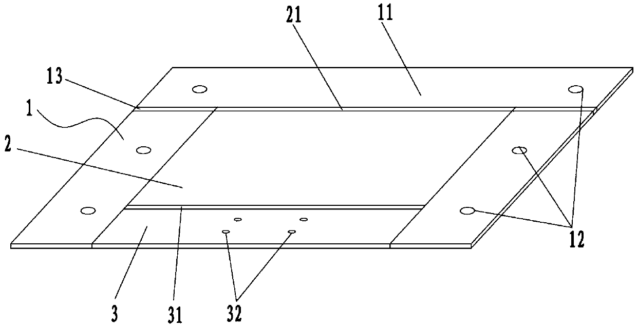
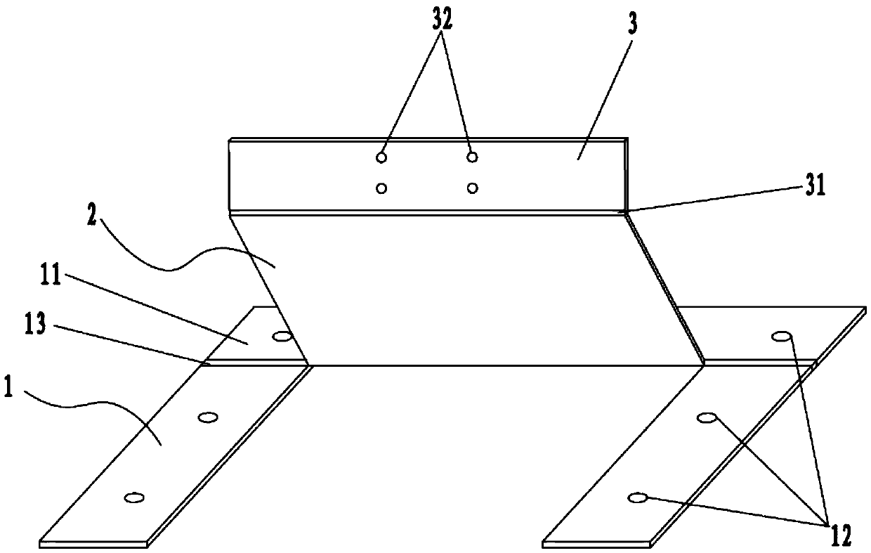
[0023] Such as figure 1 or 2, the stent structure of the present invention includes: a stent main body 1, a first connecting plate 2 and a second connecting plate 3, the stent main body 1 is in a U-shaped structure, and the first connecting plate 2 passes through the first damping The rotating shaft 21 is rotatably connected in the U-shaped structure of the bracket main body 1, and the second connecting plate 3 is rotatably connected to the side of the first connecting plate 2 away from the first damping rotating shaft 21 through the second damping rotating shaft 31. The two sides of the U-shaped structure of the main body 1 are provided with a plurality of first installation holes 12 matching with the installation plane; the middle part of the second connecting plate 3 is provided with a number of second installation holes 32 for matching with the display device.

[0024] Wherein, the first connecting plate 2 is rotatably connected to the side of the U-shaped structure of the...

Embodiment 2

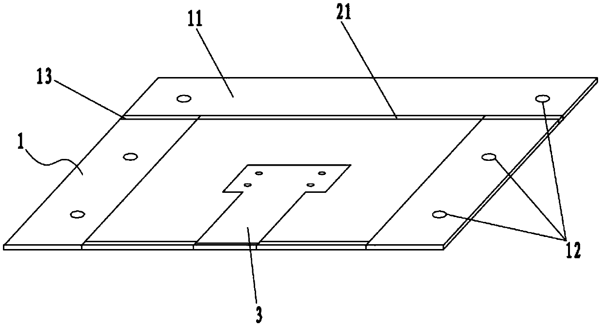
[0030] Such as image 3 or Figure 4 As shown, this embodiment is roughly the same as Embodiment 1, the difference is that: the side of the first connecting plate 2 close to the second connecting plate 3 is also provided with a container adapted to the outline of the second connecting plate. The second connecting plate 3 is rotatably connected to the first connecting plate 2 and can be flipped and folded in the receiving groove 22 .

[0031] Further, the second connecting plate 3 is a T-shaped structure, and the accommodating groove 22 is a T-shaped groove structure corresponding thereto.

[0032] Further, the accommodating groove 22 runs through both ends of the first connecting plate 2 .

[0033] The present invention adopts the above-mentioned technical solution, and when the first connecting plate 2 and the second connecting plate 3 are folded in the U-shaped structure of the main body 1, the bracket structure can present a regular flat structure, so that it can save pac...


PUM


Abstract

The invention discloses a supporting structure of display equipment. The supporting structure comprises a support main body, a first connecting plate and a second connecting plate, wherein the supportmain body is of a U-shaped structure, the first connecting plate is rotationally connected into the U-shaped structure of the support main body through a first damping rotating shaft, the second connecting plate is rotationally connected to one side, away from the first damping rotating shaft, of the first connecting plate through a second damping rotating shaft, and a plurality of first mountingholes matched with the mounting planes are formed in the two sides of the U-shaped structure of the support main body; a plurality of second mounting holes matched with the display equipment are formed in the middle of the second connecting plate, and after the display equipment is installed and fixed, the height in the vertical direction can be adjusted through the overturning of the first connecting plate, and the front inclination or the backward inclination of the display surface of the display equipment can be realized through the overturning of the second connecting plate, so that the visual angle of the display equipment can be adjusted.

Description

technical field [0001] The invention relates to the field of supporting devices, in particular to a display device support structure. Background technique [0002] Existing display device brackets are usually split-type, among which, for small-sized display devices, it can be divided into two parts: the bracket and the base; for large-sized display devices, it can be divided into two independent brackets on the left and right, or an integrated complete bracket . [0003] However, regardless of whether it is a split type or an integrated type, due to the superimposed thickness (or height) of the base and the bracket or the structural irregularity, it takes up a lot of space during packaging. It not only increases the difficulty of packaging design, but also directly affects the loading capacity due to taking up more space. Contents of the invention [0004] In view of the situation in the prior art, the purpose of the present invention is to provide a display device suppo...

Claims


Application Information

Patent Timeline
IPC IPC(8): F16M11/38
CPCF16M11/38
Inventor 欧阳晓辉
Owner TPV DISPLAY TECH CHINA
Why Eureka
Try Eureka