Compression coding methods
A technology of compression coding and direction prediction, applied in image communication, digital video signal modification, electrical components and other directions, can solve problems such as occupying a large storage space and channel bandwidth, large amount of video information data, and restricting the expansion of the video communication industry. Achieve the effect of saving the number of transmitted bits, increasing the bandwidth compression rate, and reducing the theoretical limit entropy
- Summary
- Abstract
- Description
- Claims
- Application Information
AI Technical Summary
Problems solved by technology
Method used
Image

Examples
Embodiment 1
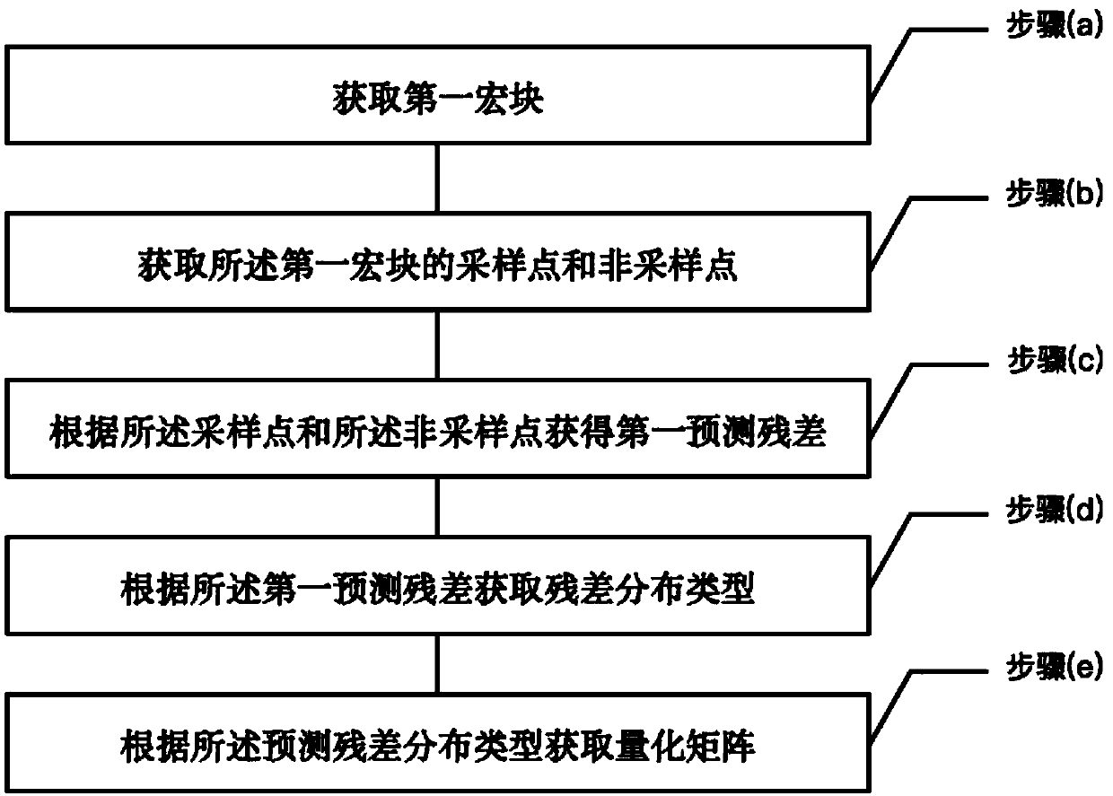
[0044] See figure 1 , figure 1 It is a schematic flow chart of a compression coding method provided for an embodiment of the present invention; the compression coding method includes the following steps:
[0045] (a) acquiring the first macroblock;
[0046] (b) acquiring sampling points and non-sampling points of the first macroblock;
[0047] (c) obtaining a first prediction residual according to the sampling point and the non-sampling point;
[0048] (d) obtaining a residual distribution type according to the first prediction residual;
[0049] (e) obtaining a quantization matrix according to the distribution type of the prediction residual;
[0050] (f) Obtaining a quantization residual according to the quantization matrix and the first prediction residual.
[0051] For images with complex textures, the embodiments of the present invention greatly improve the prediction accuracy of the texture at the boundary, reduce the theoretical limit entropy, and increase the band...
Embodiment 2
[0053] see again figure 1 In this embodiment, on the basis of the foregoing embodiments, the compression coding method will be described in detail. Specifically, in the method, step (b) also includes:
[0054] (a) acquiring the first macroblock;
[0055] (b) acquiring sampling points and non-sampling points of the first macroblock;
[0056] (c) obtaining a first prediction residual according to the sampling point and the non-sampling point;
[0057] (d) obtaining a residual distribution type according to the first prediction residual;
[0058] (e) obtaining a quantization matrix according to the distribution type of the prediction residual;
[0059] (f) Obtaining a quantization residual according to the quantization matrix and the first prediction residual.
[0060] Wherein, step (b) comprises:
[0061] (b1) sequentially obtaining the difference between each pixel value of the first macroblock and the previous pixel value to form a residual sequence;
[0062] (b2) Obtai...
Embodiment 3
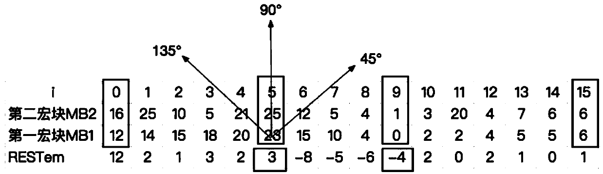
[0088] see again figure 1 with figure 2 , figure 2 It is a schematic diagram of a prediction residual calculation principle of a compression coding method provided by an embodiment of the present invention. On the basis of the above-mentioned embodiments, this embodiment focuses on an example to describe the compression coding method in detail. Specifically, assume that the size of the first macroblock MB1 to be processed is m×n pixels, where m and n are both greater than 0 an integer of . The following embodiment takes m=16, n=1 as an example for illustration, the first macroblock MB1 to be processed={12, 14, 15, 18, 20, 23, 15, 10, 4, 0, 2, 2, 4 , 5, 5, 6} specifically include the following steps:
[0089] S10: Form a residual sequence by taking the difference between each bit of the pixel value of the first macroblock MB1 and the previous bit of pixel value. that is satisfied,
[0090]
[0091] Get ResTem = {12, 2, 1, 3, 2, 3, -8, -5, -6, -4, 2, 0, 2, 1, 0, 1}; ...
PUM
 Abstract
Description
Claims
Application Information
 - R&D
- Intellectual Property
- Life Sciences
- Materials
- Tech Scout
- Unparalleled Data Quality
- Higher Quality Content
- 60% Fewer Hallucinations
Browse by: Latest US Patents, China's latest patents, Technical Efficacy Thesaurus, Application Domain, Technology Topic, Popular Technical Reports.
© 2025 PatSnap. All rights reserved.Legal|Privacy policy|Modern Slavery Act Transparency Statement|Sitemap|About US| Contact US: help@patsnap.com