Self-throwing-separating cowling and rocket
A fairing and self-throwing technology, which is applied to space navigation equipment, space navigation vehicles, space navigation equipment, etc., to achieve the effects of overcoming resistance and high temperature environment, fast separation speed, and stable and reliable output performance
- Summary
- Abstract
- Description
- Claims
- Application Information
AI Technical Summary
Problems solved by technology
Method used
Image
Examples
Embodiment 1
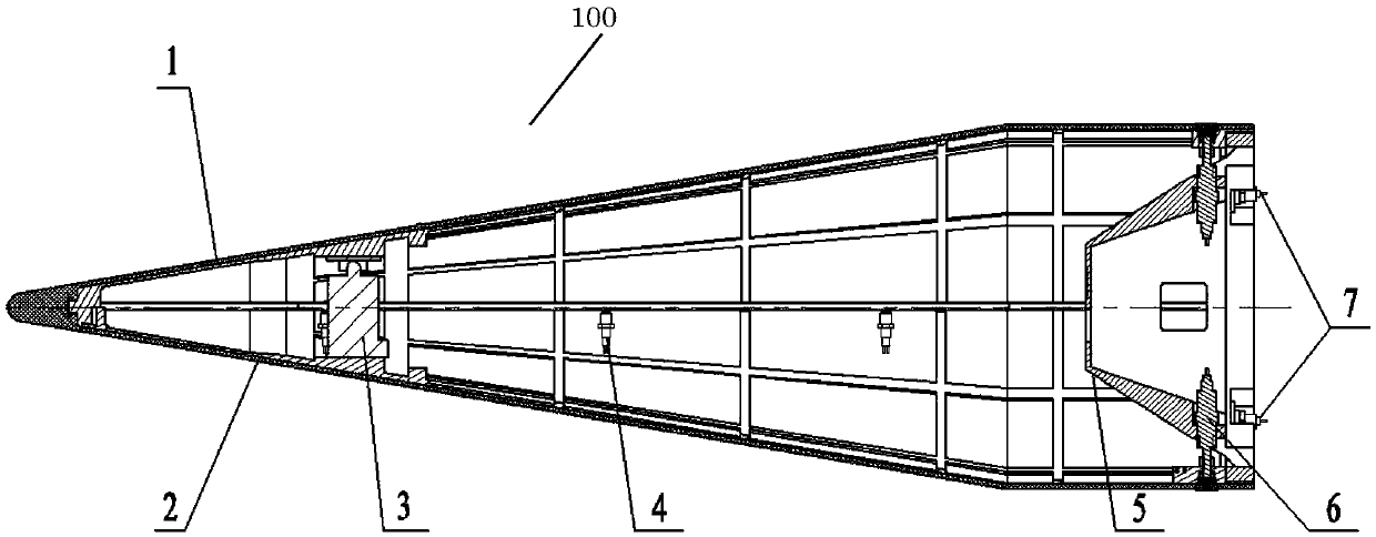
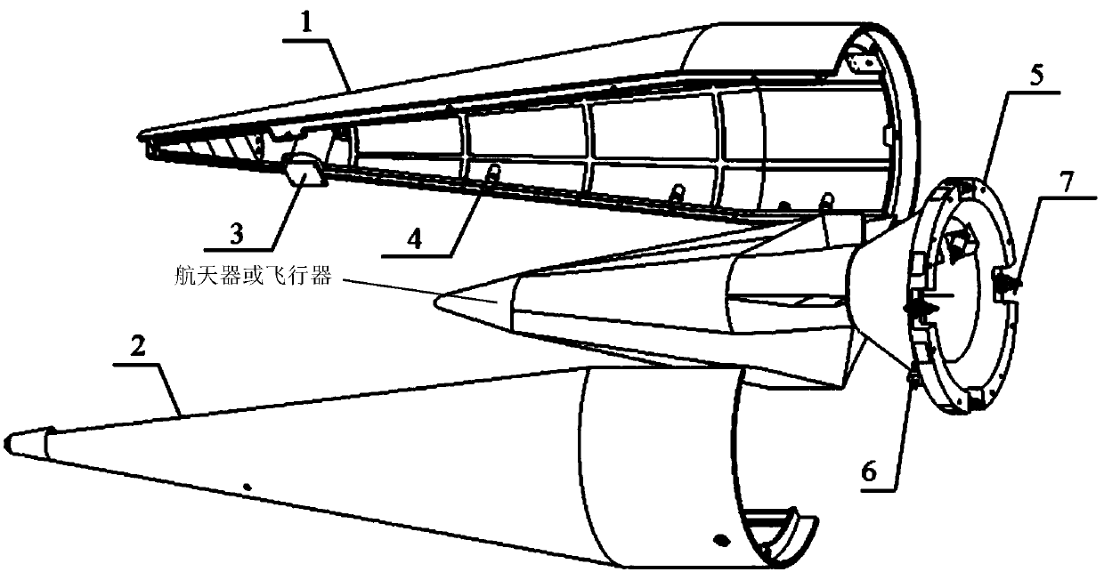
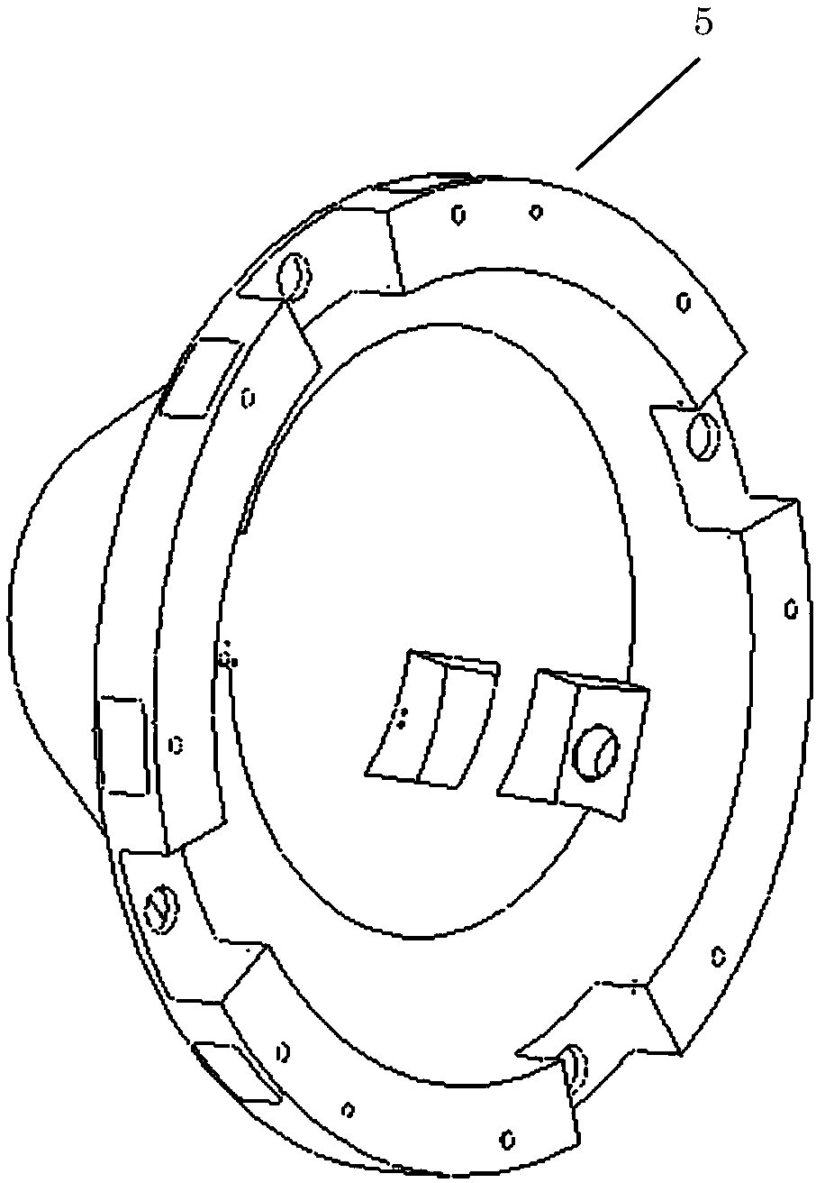
[0050] Such as figure 1 As shown, the self-throwing fairing 100 is connected with the head of the rocket body through the docking bracket 5, including:
[0051] The fairing casing includes at least two fairing pieces, and the fairing pieces are at least spliced and connected by a radial connection mechanism.
[0052] The shroud separation system receives the control command of the rocket body and operates, including a separation output mechanism and an axial connection mechanism arranged in the fairing casing. The axial connection mechanism is used to connect the docking bracket 5 and the fairing casing.
[0053] Wherein, the separation output mechanism is used to push the spinner shell to separate according to a predetermined separation speed and attitude after the connection between the radial connection mechanism and the axial connection mechanism is released.
Embodiment 2
[0055] On the basis of Embodiment 1, as a specific preference, the radial connection mechanism is a radial connection separation bolt 4, which is arranged in the middle of the fairing sheet body, and is used to connect at least two split fairing sheet bodies, When the breakaway bolt receives the breakaway signal, it acts to release or weaken the connection; and / or
[0056] The axial connection mechanism is an axial connection separation bolt 7, which is arranged at the tail of the fairing sheet body, and is used to axially connect and fix the fairing shell and the docking bracket, such as image 3 , 5 As shown in , 7, the axial connection separation bolt 7 is used to connect the docking bracket and the control cabin, and at the same time as Figure 5 As shown, it can be seen that the docking bracket and the control cabin are auxiliary connected by the stud bolt S. When the separation bolt receives the separation signal from the control cabin, it will be activated by the deton...
Embodiment 3
[0060] On the basis of Embodiment 1-2, as a specific preference, the separation output mechanism includes a front end separation output actuator 3 arranged at the inner head of the fairing shell, and the two ends of the front end separation output actuator are respectively connected to the corresponding The corresponding interface connection set on the adjacent fairing body, such as figure 2 , 3 As shown, when the front-end separation output actuator receives the separation signal, it will act to open the corresponding fairing sheet for separation; and / or
[0061] The separation output mechanism includes the rear end separation output actuator 6 arranged at the rear part of the fairing shell, and the rear end separation output actuator has a body 61 and a push rod 62, such as Image 6 , 9 , 10, 11, and 12, the body is an airtight cavity, and the inside is equipped with prefabricated powder blocks and detonators (current detonators, such as electric detonators). Gas, expans...
PUM
 Abstract
Description
Claims
Application Information
 - R&D
- Intellectual Property
- Life Sciences
- Materials
- Tech Scout
- Unparalleled Data Quality
- Higher Quality Content
- 60% Fewer Hallucinations
Browse by: Latest US Patents, China's latest patents, Technical Efficacy Thesaurus, Application Domain, Technology Topic, Popular Technical Reports.
© 2025 PatSnap. All rights reserved.Legal|Privacy policy|Modern Slavery Act Transparency Statement|Sitemap|About US| Contact US: help@patsnap.com


