
Rifle chamber cleaning tool with debris capturing recesses

a cleaning tool and debris technology, applied in the direction of hollow object cleaning, hair combs, mechanical equipment, etc., can solve the problems of inoperable firearms, inconvenient cleaning of firing chambers of all types of firearms, contamination and fouling of firing chambers, etc., to achieve safe and faster method of debris removal and rapid debris removal

Active Publication Date: 2012-08-28
LIKEMIND BRANDS INC
View PDF23 Cites 17 Cited by
  • Summary
  • Abstract
  • Description
  • Claims
  • Application Information

AI Technical Summary

Benefits of technology

[0022]The present embodiment is specifically designed to remove debris from the breech and locking lugs of the AR-1S and M-16 family of rifles. And it finds particular application as a tool for performing immediate action, in a field environment. In the case of the M-16 family of rifles, the rear of the rifle breech or chamber is comprised of eight locking lugs, spaced evenly at forty-five degrees around the perimeter of the chamber. The chamber locking lugs are engaged by seven locking lugs of the bolt. (The bolt design utilizes only seven locking lugs, in order to use one lug-space for a claw-type spent cartridge extractor.) With a manually operated bolt action firearm the operator can apply an increasing amount of force upon the rifle bolt to overcome the resistance of accumulated debris.
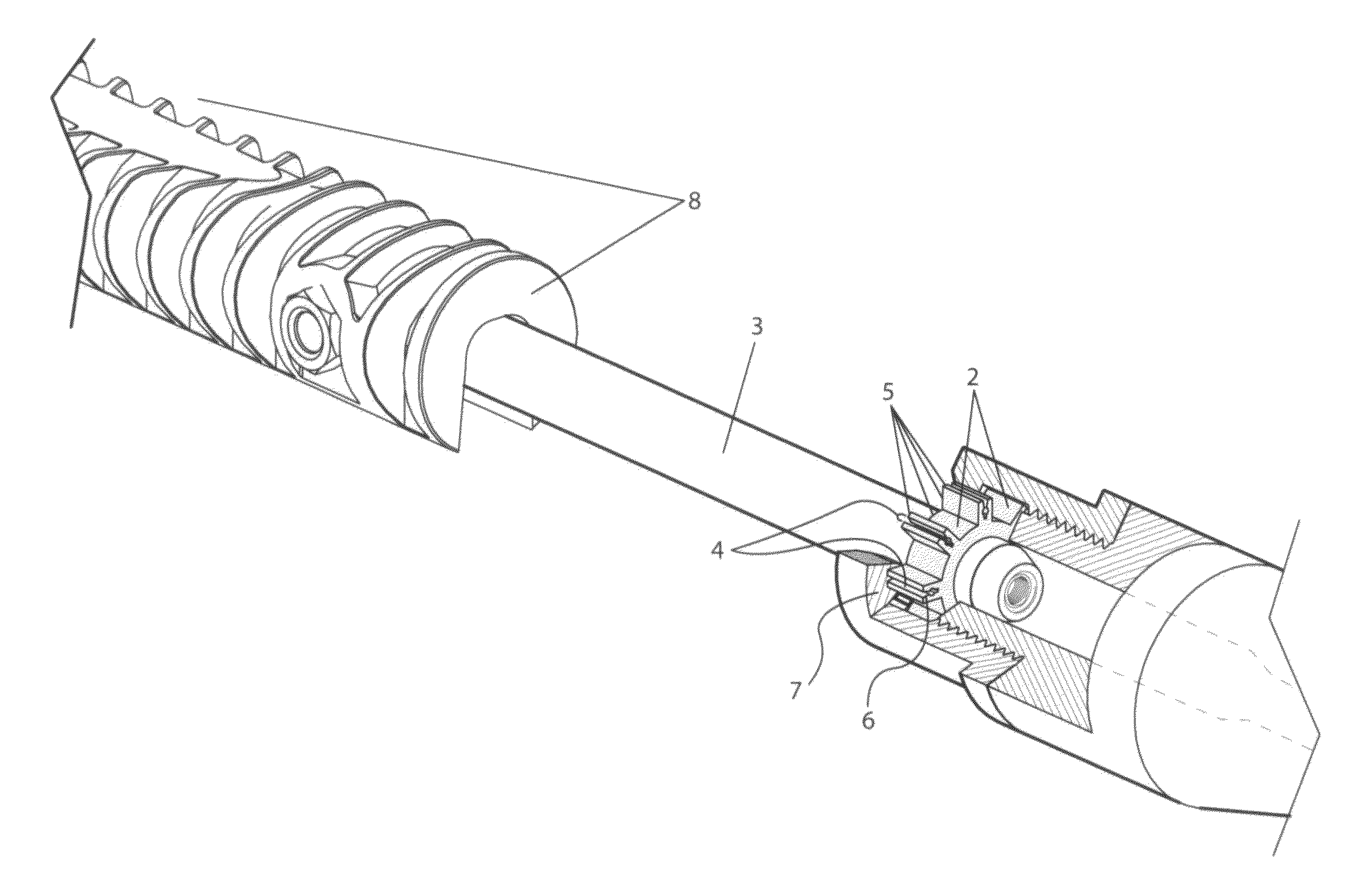
[0024]Accordingly, the present embodiment provides a foldable, field transportable, and specially formed hand operated cleaning tool. A one-step cleaning of the chamber locking lugs of the M16 / AR-15 family of rifles is now possible. Said embodiment provides uniquely formed debris capturing recesses whose advantages for rapid debris removal in the field have remained heretofore un-discovered. By virtue of the present embodiment, a safer and faster method of debris removal has advanced the art. Said method can easily be employed under the harshest of field conditions.

Problems solved by technology

The firing chambers of all types of firearms are subjected to contamination and fouling due to gunpowder residues.
Contaminants such as carbon, sand, and shavings from the metal cartridge cases become attached to the locking lugs.
Said contamination and fouling has often led to an inoperative firearm.
Unexpected stoppages of the firearm can become life threatening emergencies for the operator.
Due to their outdated design, brushes, mops, and their associated methods are less effective than the presently claimed embodiment.
Additionally, said chemicals may present hazards to the skin and eyes of the user.
Chemicals may also prove very cumbersome to apply under field conditions, and can actually attract dirt and sand.
First, brushes that are flexible enough to be inserted into the chamber locking lugs are not rigid enough to scrape away metal fragments that have become affixed to the breech by high heat and pressure.
A second weakness of the brush and mop method is the reliance on a set of attachments that is threaded onto a cleaning rod.
The operator may turn the cleaning rod in the wrong direction under stress.
The brush can become unthreaded and left inside the breech rendering the firearm inoperative.
One major problem with said dental tools is inaccuracy at locating the exact location of an obstruction inside of the rifle chamber.
Additionally, under conditions of poor lighting, all of the aforementioned prior art clearly falls short of the claimed embodiment.
Said patent issued for a “Locking Lug Pick for Firearm Cleaning” calls attention to the need for a tool to clean the locking lug area of a firearm, but unlike the claimed embodiment, it fails to include a means for removal of debris.
But, the claim of “removing built-up carbon deposits from the interior of the firearm” clearly falls short of the current embodiment.
Finally, the expandable, cam-like, plug mechanism of U.S. Pat. No. 3,765,045, Schneider, et al introduces a substantial risk.
This could occur, perhaps due to debris contamination.
Said mechanism would remain stuck in the chamber rendering the weapon totally inoperative.
Yet, all three examples completely fail to address the manner in which the carbon is actually transported from the inside of the firearm.
Quite often, the first indication of excessive debris build-up is a failure of the rifle's bolt to fully close on a cartridge case in the chamber.

Method used


Image

  • Rifle chamber cleaning tool with debris capturing recesses
  • Rifle chamber cleaning tool with debris capturing recesses
  • Rifle chamber cleaning tool with debris capturing recesses

Examples


Embodiment Construction

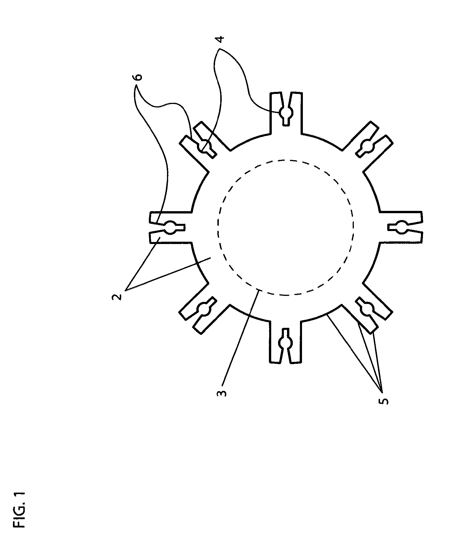
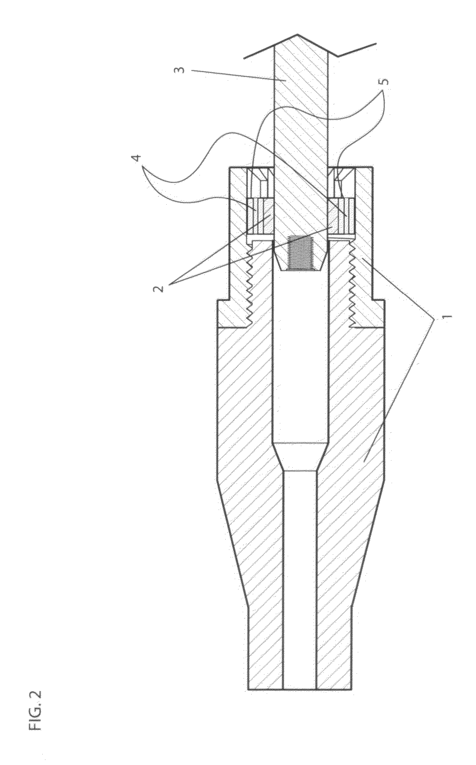
[0039]FIG. 1 shows a rear facing view of the annular main body of the scraping head with elongated fingers (2). The scraping head (2) is preferably comprised of any suitable and durable material, including, but not limited to, metal and plastic. The scraping head (2) can be formed through various industrial processes such as water-jet cutting, laser jet cutting, investment casting, injection molding or wire (EDM) electrode discharge machining. The scraping head (2) is then permanently affixed, by pinning, set screws, welding, soldering, or other means, to the tool shaft (3) so that it cannot become “unthreaded” and left inside the rifle chamber, rendering the firearm inoperable. The debri capturing chamber (4) is formed by two opposing scraping edges within the elongated fingers of the scraping head. (2) Two opposed angled scraping edges (6) form the narrow entrance of the debris capturing chamber. Depending upon the method of manufacture, the debris capturing chambers, which face r...


PUM


Abstract

A rifle chamber cleaning tool comprising a single piece of material with an annular scraping head and a plurality of elongated fingers, comprising debris capturing chambers within the elongated fingers. The scraping head and fingers are shaped so as to fit snugly when inserted between the lug recesses inside the rifle chamber. The distance between the fingers is roughly equivalent to the distance between the locking lugs inside the rifle chamber.

Description

CROSS-REFERENCE TO RELATED APPLICATION[0001]This application claims the benefit of provisional patent application Ser. No. 61 / 281,737, filed 2009 Nov. 23 by the present inventor.BACKGROUNDPrior Art[0002]The following is a tabulation of some prior art that presently appears relevant:[0003]U.S. PatentsU.S. Pat. No.Kind CodeIssue DatePatentee3,765,045B1Oct. 16, 1973Schneider et alD562,935SFeb. 26, 2008Morgan3,602,935B1Sep. 7, 1971 McDonnell et al1,872,198B1Aug. 16, 1932Van Rixel5,588,242B1Dec. 31, 1996HughesD601,688SOct. 6, 2006Abe et alD589,579SMar. 31, 2009Williams4,930,240B1Jun. 5, 1990Bice4,873,778B1Oct. 17, 1989Stipp4,843,750B1Jul. 4, 1989BlaséD375,595SNov. 12, 1996Shumway et al5,557,871B1Sep. 24, 1996LaLonde[0004]U.S. Patent Application PublicationsPublication No.Kind CodeIssue DateApplicant20040244627A1Dec. 9, 2004Bice[0005]Foreign Patent DocumentsForeign Cntry Kind App orDoc. No.CodeCodePub. Dt.Patentee2007087003USA2Aug. 2, 2007Cioletti et al2007046856USA2Apr. 26, 2007WilliamsN...

Claims


Application Information

Patent Timeline
Patent Type & Authority Patents(United States)
IPC IPC(8): F41A29/02
CPCF41A29/02
Inventor JOHNSON, SAM GILLIAM
Owner LIKEMIND BRANDS INC
Learn More