High pressure paint pump

a paint pump and high-pressure technology, applied in the field of painting pumps, can solve the problems of affecting the service life of the pump, the leakage of the pump during operation, and the failure of the pump to operate normally, so as to overcome the resistance of the upper and lower seal packing, increase the access to the inlet valve elements, and avoid the effect of leakag

Active Publication Date: 2016-03-10
TRITECH INDS
View PDF12 Cites 20 Cited by
  • Summary
  • Abstract
  • Description
  • Claims
  • Application Information

AI Technical Summary

Benefits of technology

[0005]It is, therefore, a primary object of the present invention to provide a paint pump adapted to pressurize paint so that the paint can be atomized and sprayed onto a surface by means of a spray gun wherein the parts and components of the pump are so constructed and arranged as to provide maximum accessibility, ease of disassembly and mistake-proof reassembly of the pump.
[0006]The above object, as well as others which will hereinafter become apparent, is accomplished in accordance with the present invention by a high pressure, double acting piston paint pump which is an improvement over prior art pumps wherein the accessibility of the inlet valve elements is increased, the upper and lower packing seals located in the pump body can be installed in the proper orientation thereof without error, and the piston can be easily assembled with the pump cylinder and properly aligned therewith without the need for special tools or undue effort. The pump according to the present invention includes a piston guide / retainer wherein the inlet valve cage is formed integral therewith and the guide is inserted into the well of the inlet valve housing so as to retain the inlet valve seat and inlet ball valve at the bottom of the well at the inlet. Thus, upon removal of the piston guide / retainer from the inlet valve housing well, the valve cage is likewise removed whereby the ball valve and inlet valve seat are accessible and easily removed. In assembling the piston with the pump cylinder, the piston head is inserted into the piston guide / retainer disposed in the inlet valve housing thereby stabilizing the piston and serving to center and guide the piston during assembly with the pump cylinder. According to another aspect of the invention, both the upper and lower packing seals are designed to be positionable in the cylinder of the pump body so that the correct orientation of the sealing lips is easily sustainable. According to yet another aspect of the invention, means are provided permitting co-operation between the inlet valve housing and the pump body or fluid housing during assembly of the piston rod with the pump cylinder whereby the piston is driven into the cylinder by a uniform and steady pressure which overcomes the resistance of the upper and lower seal packings.

Problems solved by technology

For the most part the only maintenance required for such pumps is the replacement of parts or components which are subject to wear, Such replacement of worn parts requires a rebuilding or refurbishing of the pump and generally involves the replacement of the packings or seals in the pumps which eventually leak as a result of wear and the replacement of the inlet and bypass valves which are also subject to wear and leakage.
However, because of the relatively complex nature of pump construction and arrangement of the parts therein, rebuilding of the pump and reassembly of the parts thereof requires special care and close attention and sometimes the use of special tools in order to insure a correct and proper rebuilding and reassembly, otherwise, damage or leakage in operation may result.
If these seals are incorrectly oriented during assembly of the pump, improper sealing will result and leakage will occur.
It is also critical during reassembly of the pump that the piston rod be properly centered and aligned for insertion into the pump cylinder otherwise again the seals may be damaged causing the pump to leak during operation.
However, pumps rebuilt by painting contractors or their employees frequently leak in operation or are otherwise damaged because of the difficulty of such rebuilding or the inability or failure to follow rebuilding instructions carefully.
The obvious drawbacks to this are the extended period of time that the pump is unavailable to the contractor and the expense therefor.
Another problem relating to the rebuilding of such pumps concerns the replacement of worn valves particularly the lower inlet valve.
However, after a period of use in pumping paint, a residual of paint accumulates in and around the valve elements and particularly the valve cage and after drying makes it difficult to remove the valve cage from the well of the housing.

Method used


Image

  • High pressure paint pump
  • High pressure paint pump
  • High pressure paint pump

Examples


Embodiment Construction

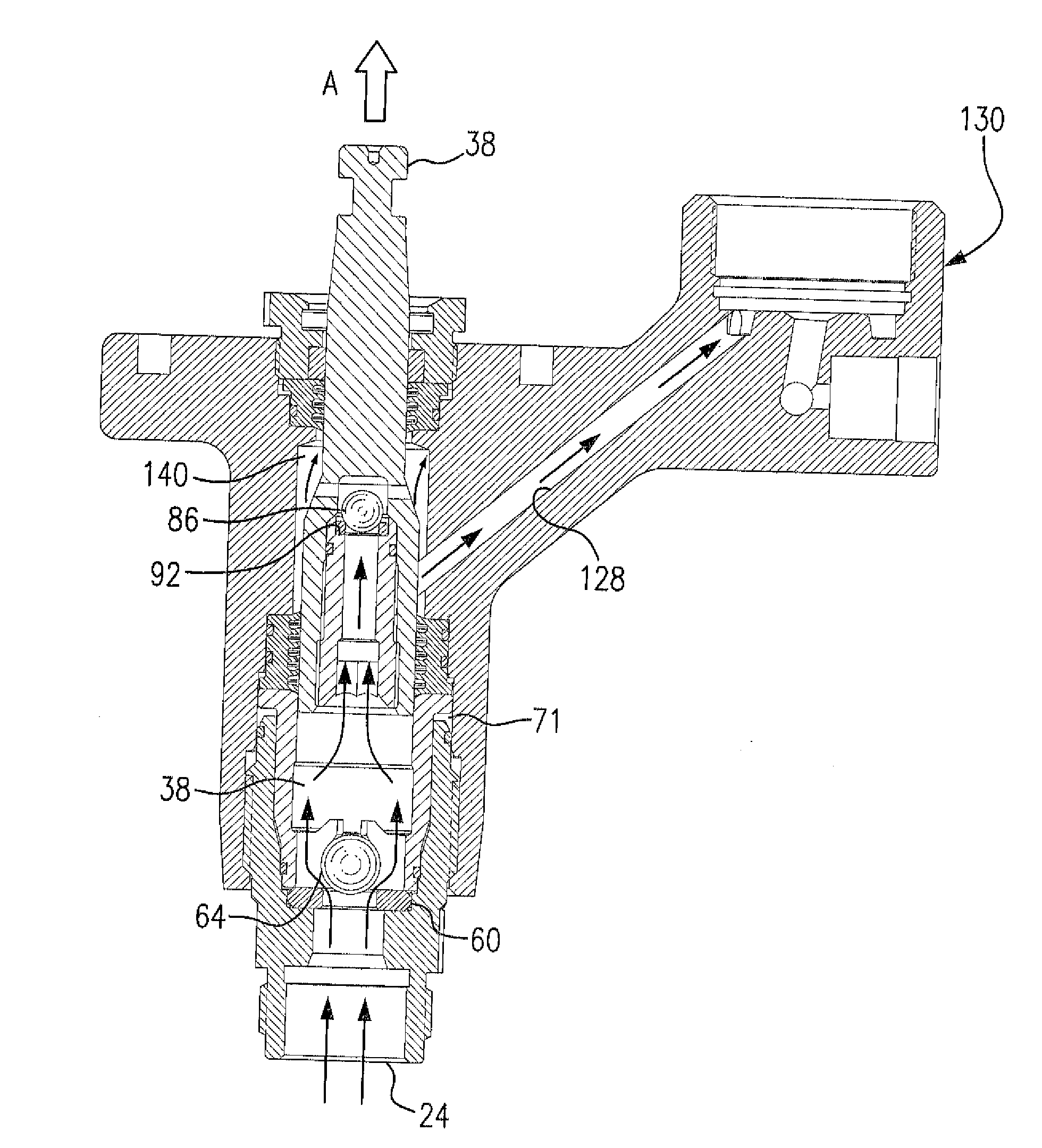
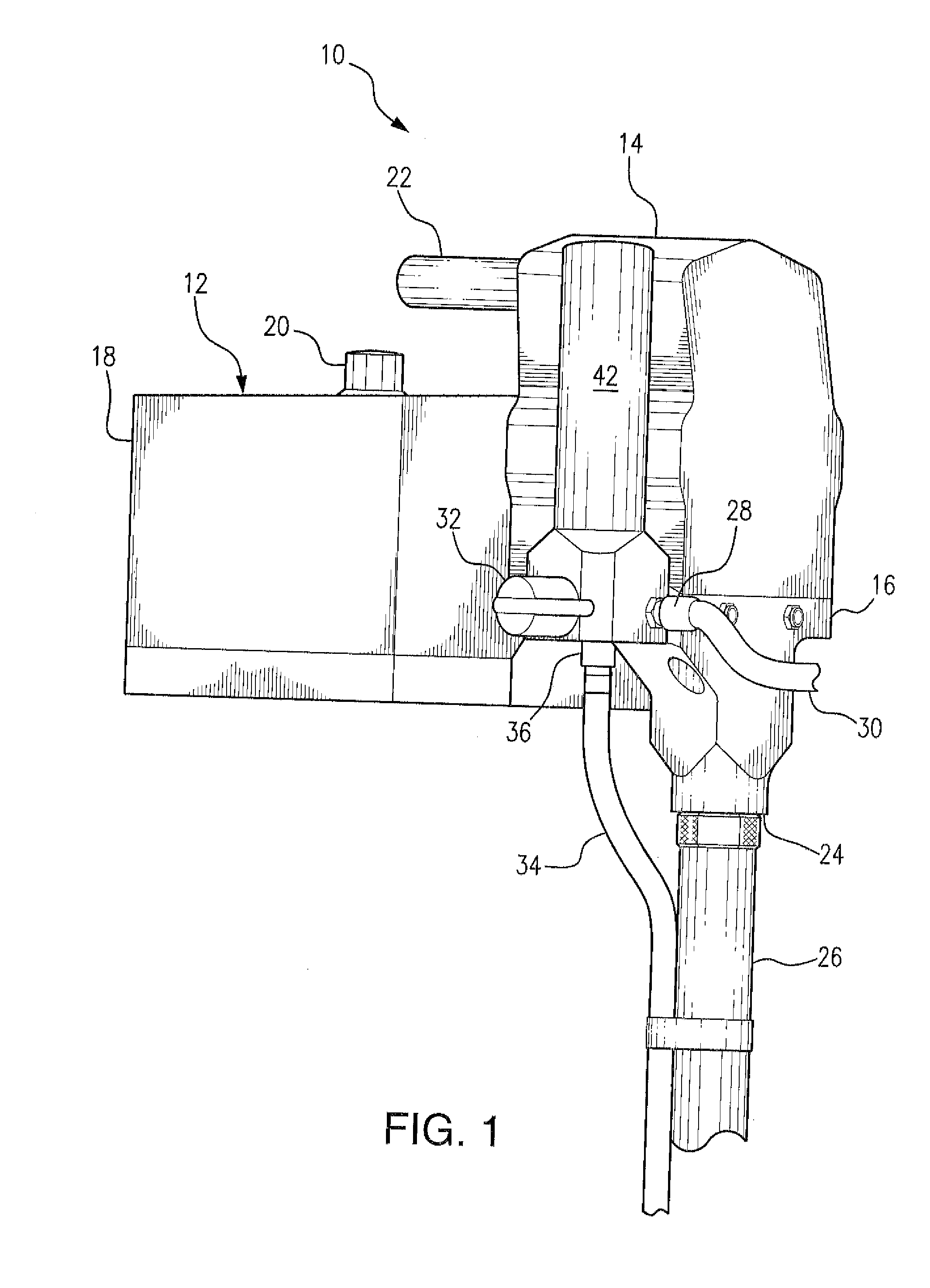
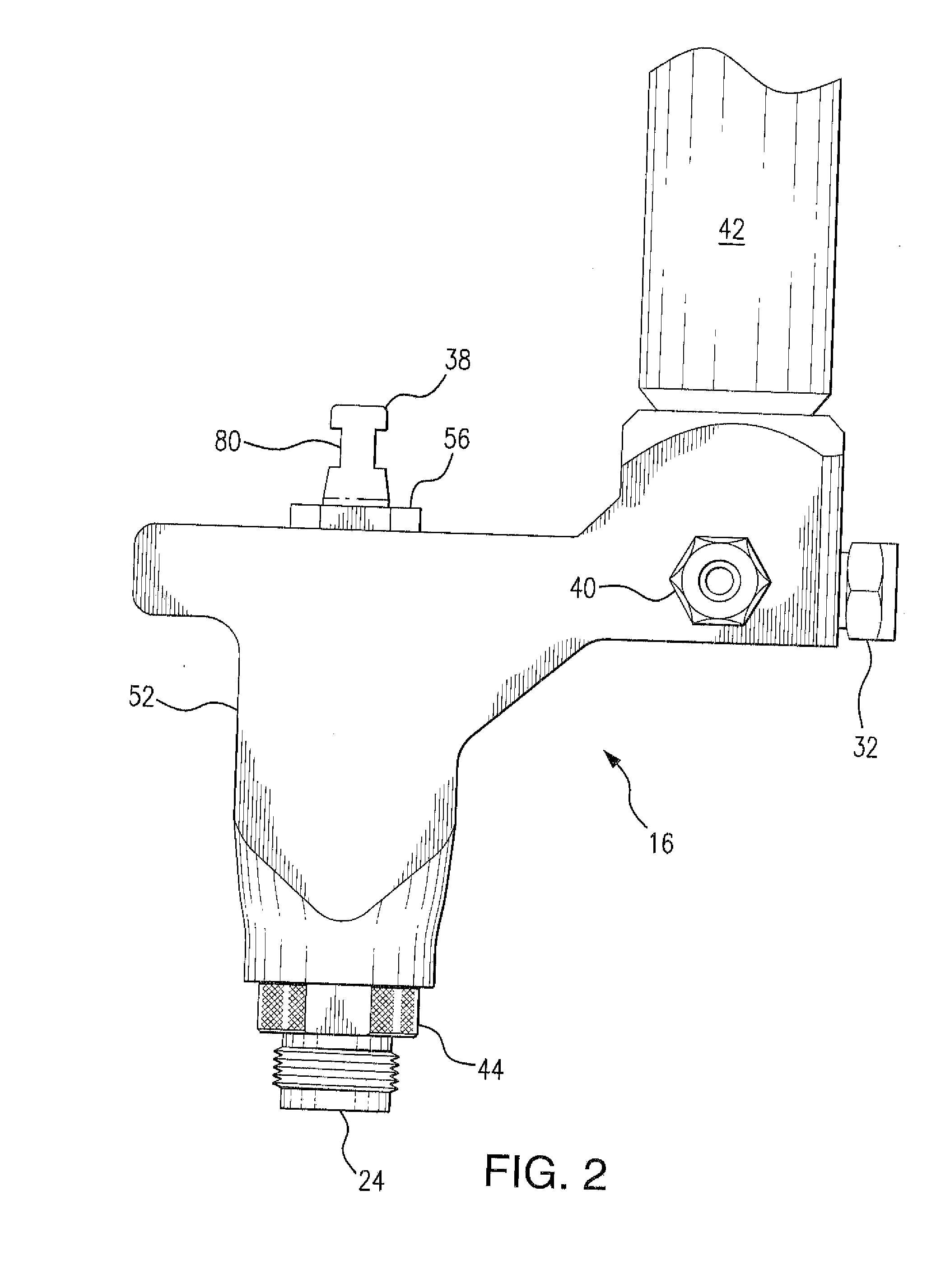
[0017]Turning to the drawings, there is shown in FIG. 1 a high pressure paint spray pump system, generally designated 10, including a motor section 12, a gear box 14 and a pump section 16. Motor section 12 includes an electric motor whose drive shaft drives the pump of pump section 16 through a reduction gear and crank shaft housed in gear box 14. A motor controller, designated 18, controls the operation of the motor through an on / off switch (not shown) and a pressure control knob 20. A handle, designated 22, is provided at the top of gear box 14 to permit lifting and carrying of pump system 10. The inlet 24 of pump section 16 is connected by means of down tube 26 to a source (not shown) of paint such as a bucket or container of paint. The outlet 28 of pump section 16 communicates via a high pressure hose 30 with a spray gun (not shown) which atomizes the high pressure paint suitable for painting. A pressure relief valve located in pump section 16 is controlled by knob 32 and permit...


PUM


Abstract

There is provided an airless paint spray pump wherein the pump is a double acting piston pump having an inlet communicating with a source of paint, a motor for driving the pump, a pressure controller for controlling the pressure of the pressurized paint delivered by the pump, and a filter for filtering the paint delivered by the pump. The pump includes features which increase the accessibility of the components thereof, prevent the incorrect installation of the seal packings in the pump cylinder, and allow the assembly of the piston in the pump cylinder properly aligned with the cylinder so as not to damage the seal packings therein.

Description

FIELD OF THE INVENTION[0001]The present invention relates generally to paint pumps adapted to pump liquid paint to such a high pressure that, upon release of the pressurized paint from a spray opening or nozzle in a spray gun, the paint is atomized and thereby rendered suitable for spray painting. More particularly, the present invention relates to an improved high pressure paint pump wherein the parts and components are so constructed and arranged as to provide maximum accessibility, ease of disassembly and mistake-proof reassembly of the parts of the pump.BACKGROUND OF THE INVENTION[0002]In hydraulic or airless paint spraying, a pump is utilized to pressurize the paint to pressures of 2,000 pounds per square inch and greater so that the paint can be atomized upon release from a nozzle in a spray gun. The type of pump preferably used for this purpose is the double acting piston pump because of the piston pump's ability to handle high viscosity paints or coatings easily and the capa...

Claims


Application Information

Patent Timeline
Patent Type & Authority Applications(United States)
IPC IPC(8): F04B53/22B05B9/04F04B5/00F04B53/10F04B53/14
CPCF04B53/22F04B53/143B05B9/0413F04B53/1095F04B53/1007F04B5/00F04B5/02F04B15/00F04B37/12F04B53/126
Inventor CAREY, DANUTA H.WALSH, CHRISTOPHER M.
Owner TRITECH INDS
Why Eureka
Try Eureka