Blank for a box, assembly of a blank and a tape for a box and a box formed from such blank and/or such assembly

a box and blank technology, applied in the field of blanks for boxes, can solve the problems of tearing of tape, affecting the sealing effect of boxes, and the application of tape to seal boxes is relatively complex, and achieves the effect of sufficient stability and easy sealing

Active Publication Date: 2018-08-07
SPARCK TECH BV
View PDF12 Cites 0 Cited by
  • Summary
  • Abstract
  • Description
  • Claims
  • Application Information

AI Technical Summary

Benefits of technology

[0020]It is an object of the invention to provide a blank as set out above allowing to fold boxes thereof having not only sufficient stability and maximum accessibility towards the inside of the box but being able to be easily sealed by a tape. In particular, the blank should be easy to cut out from corresponding material in particular in a fully automated way at automated packaging stations forming customized boxes for items to be packaged. The blank should not only allow that the box is automatically folded but that the box is automatically sealed by a tape.
[0021]Another object of the invention is to provide an alternative assembly of a blank for a box and a tape. It is a further object of the invention to provide an assembly of a blank for a box and a tape from which a box can be formed which can relatively easily be sealed by means of said tape. It is a further object of the invention to provide an assembly of a blank for a box and a tape from which a box can be formed which when sealed by means of said tape can be transported with a relative low risk of unwanted opening. Another object of the invention is to provide a blank for a box, from which relatively easy a box can be folded around articles to be packaged in an automated way. Once articles are put in the box, the box design should allow automated closing and sealing of the box by a tape.

Problems solved by technology

In both cases the application of tape to seal the box is relatively complex, which is especially a disadvantage in case of automated sealing.
Furthermore, since during handling and transport edges of a box formed out of the known blank are most prone to impact, in some cases the tape may tear during transport or handling of the box resulting in the unwanted opening of the erected box.
Especially when the seam of the box folded from the known blank is situated at the bottom, tearing of the tape can occur easily.

Method used


Image

  • Blank for a box, assembly of a blank and a tape for a box and a box formed from such blank and/or such assembly
  • Blank for a box, assembly of a blank and a tape for a box and a box formed from such blank and/or such assembly
  • Blank for a box, assembly of a blank and a tape for a box and a box formed from such blank and/or such assembly

Examples


Embodiment Construction

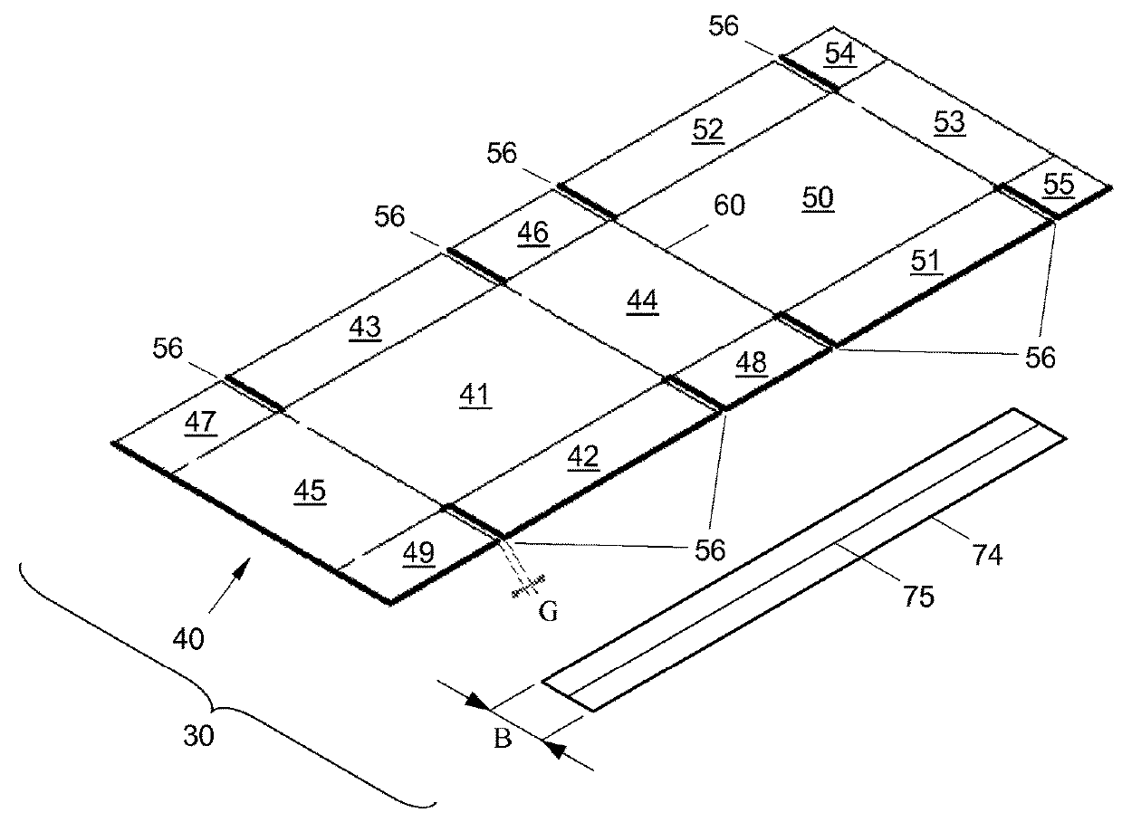
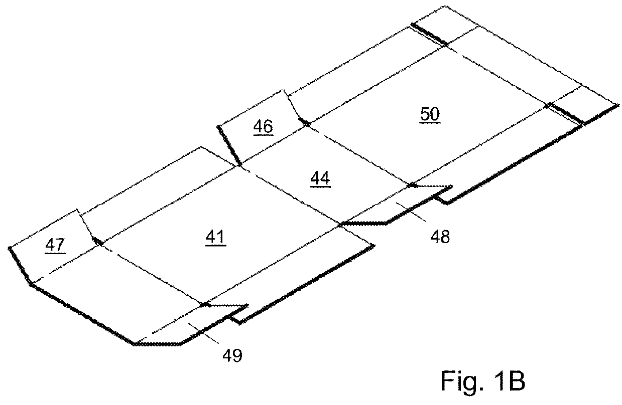
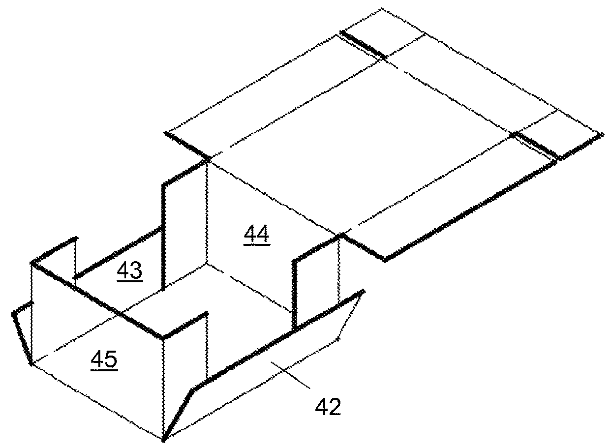
[0051]FIGS. 1A to 1E are used to generally describe an embodiment of an assembly 30 according to the invention of a tape 74 and a blank 40 is shown schematically in views in perspective of various stages of folding a box from the blank 40. The tape 74 has a breadth B and is in this embodiment integrally provided with tear means, such as a tear strip 75. In other embodiments (not shown), the tape may alternatively be free from tear means. The blank 40 has a thickness T, and in this embodiment is manufactured from card board.

[0052]In the embodiment shown (see FIG. 1A), the blank 40 has a rectangular bottom panel 41, rectangular first and second side panels 42, 43, respectively, and rectangular first and second end panels 44, 45, respectively, joined to said bottom panel 41. Rectangular first and second corner panels 46, 48, respectively, are joined to said first end panel 44. Furthermore, rectangular third and fourth corner panels 47, 49, respectively, are joined to said second end pa...


PUM


Abstract

A blank for folding a box is proposed that allows folding a box of which the only seams substantially parallel to a bottom and a top plane of the box are a seam for attaching a first side panel to a first top side panel, a seam for attaching a second side panel to a second top side panel, and a seam for attaching a top end panel to a second end panel so that the seams are formed on an external surface of the box and are situated at a same distance from the bottom panel. A corresponding blank has a rectangular bottom panel (41), a first rectangular side panel (42) joined to a first side of said bottom panel (41), a second rectangular side panel (43) joined to a second side of said bottom panel (41) opposite the first side thereof, a first rectangular end panel (44) joined to a first end of said bottom panel (41), a second rectangular end panel (45) joined to a second end of said bottom panel (41) opposite the first end of said bottom panel (41) and having a free end side opposite said second end of said bottom panel (41), a first rectangular corner panel (46) joined to a first side of said first end panel (44), a second rectangular corner panel (48) joined to a second side of said first end panel (44) opposite the first side thereof, a third rectangular corner panel (47) joined to a first side of said second end panel (45), a fourth rectangular corner panel (49) joined to a second side of said second end panel (45) opposite the first side thereof, a rectangular top panel (50) joined to said first end panel (44) such that it is arranged at the side of said first end panel (44) opposite to the side where said bottom panel (41) is joined to said first end panel (44), a first rectangular top side panel (51) joined to a first side of said top panel (50), a second rectangular top side panel (52) joined to a second side of said top panel (50) opposite the first side thereof, and a rectangular top end panel (53) joined to said top panel (50) such that it is arranged at the side of said top panel (50) opposite to the side where said first end panel (44) is joined to said top panel (50), wherein said top side panels (51, 52) each have a width (H2+t) that substantially corresponds to the half of the length (H+2t; H+t) of each of the first and the second end panels (44; 45) and wherein said top end panel (53) has a length (H2+t) that substantially corresponds to the half of the length (H+2t; H+t) of each of the first and the second end panels (44; 45).

Description

TECHNICAL FIELD OF INVENTION[0001]The invention relates to a blank for a box, in particular for automatically folding a box from said blank. The invention also relates to an assembly of a blank and a tape for a box and a box formed from such blank respectively such assembly.BACKGROUND OF THE INVENTION[0002]Blanks for boxes having[0003]a rectangular bottom panel, a first rectangular side panel joined to a first side of said bottom panel,[0004]a second rectangular side panel joined to a second side of said bottom panel opposite the first side thereof,[0005]a first rectangular end panel joined to a first end of said bottom panel,[0006]a second rectangular end panel joined to a second end of said bottom panel opposite the first end of said bottom panel and having a free end side opposite said second end of said bottom panel,[0007]a first rectangular corner panel joined to a first side of said first end panel,[0008]a second rectangular corner panel joined to a second side of said first e...

Claims


Application Information

Patent Timeline
Patent Type & Authority Patents(United States)
IPC IPC(8): B65D5/02B65D5/20
CPCB65D5/0236B65D5/2052B65D5/0227
Inventor SYTEMA, HERMAN
Owner SPARCK TECH BV
Why Eureka
Try Eureka