Lifting device

a technology for lifting devices and support arms, applied in the direction of lifting devices, lifting frames, etc., can solve the problem of pivoted support arms, and achieve the effect of good accessibility

Active Publication Date: 2020-09-29
FINKBEINER GERHARD
View PDF29 Cites 3 Cited by
  • Summary
  • Abstract
  • Description
  • Claims
  • Application Information

AI Technical Summary

Benefits of technology

[0007]The present invention provides a lifting device as well as a lifting platform to lift and lower loads, vehicles or similar, which has, on the one hand, an accessibility which is as great as possible to the vehicle for assembly, maintenance or repair work and, on the other hand, enables a quick lifting lowering of the vehicle.
[0024]A preferred embodiment of the lifting platform provides that each pair of lifting devices which are allocated to each other, have a right and a left load receiver, such that the lifting devices stand opposite one another, crossways with regard to the orientation thereof. The lifting columns can thereby each be positioned in outer corner regions with respect to the work region, whereby a maximum accessibility of the work region is created.

Problems solved by technology

The aforesaid lifting device has the advantage of a good accessibility to the underbody of the lifted vehicle, but has the disadvantage that the pivotable support arms must be pivoted manually out of the vehicle region for driving the vehicle on and off the lifting device and must be positioned exactly on the holding devices of vehicle provided therefor for each vehicle.
In particular, this is time-consuming during series inspection of vehicles.

Method used


Image

  • Lifting device
  • Lifting device
  • Lifting device

Examples


Embodiment Construction

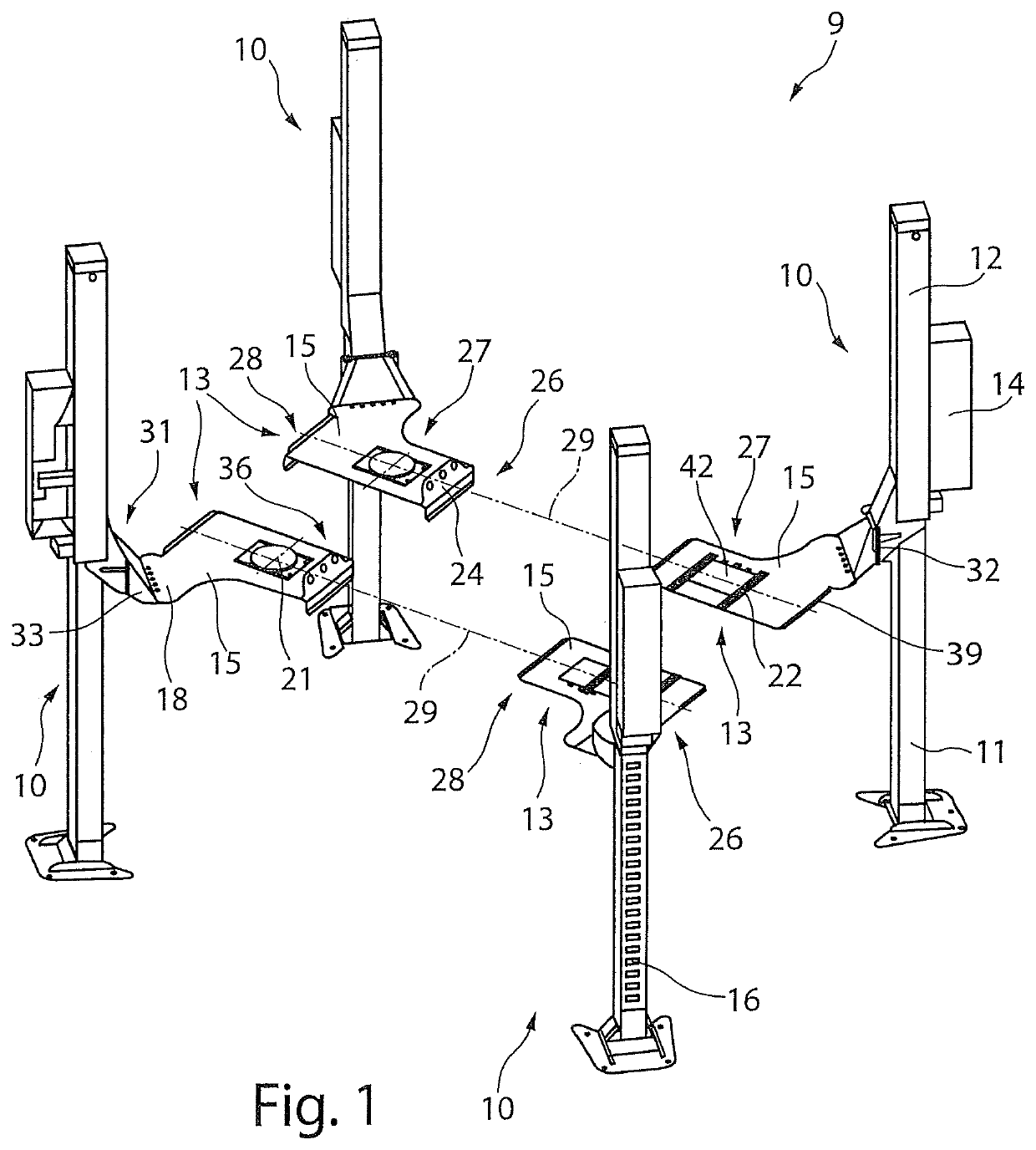
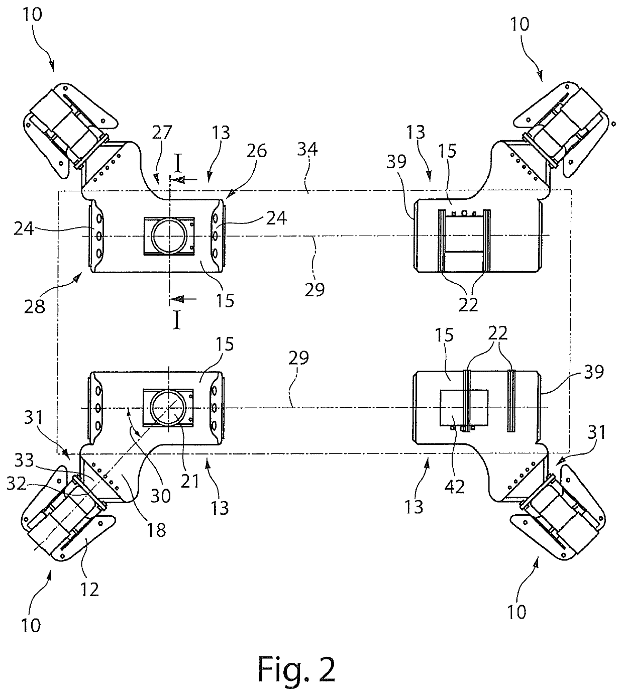
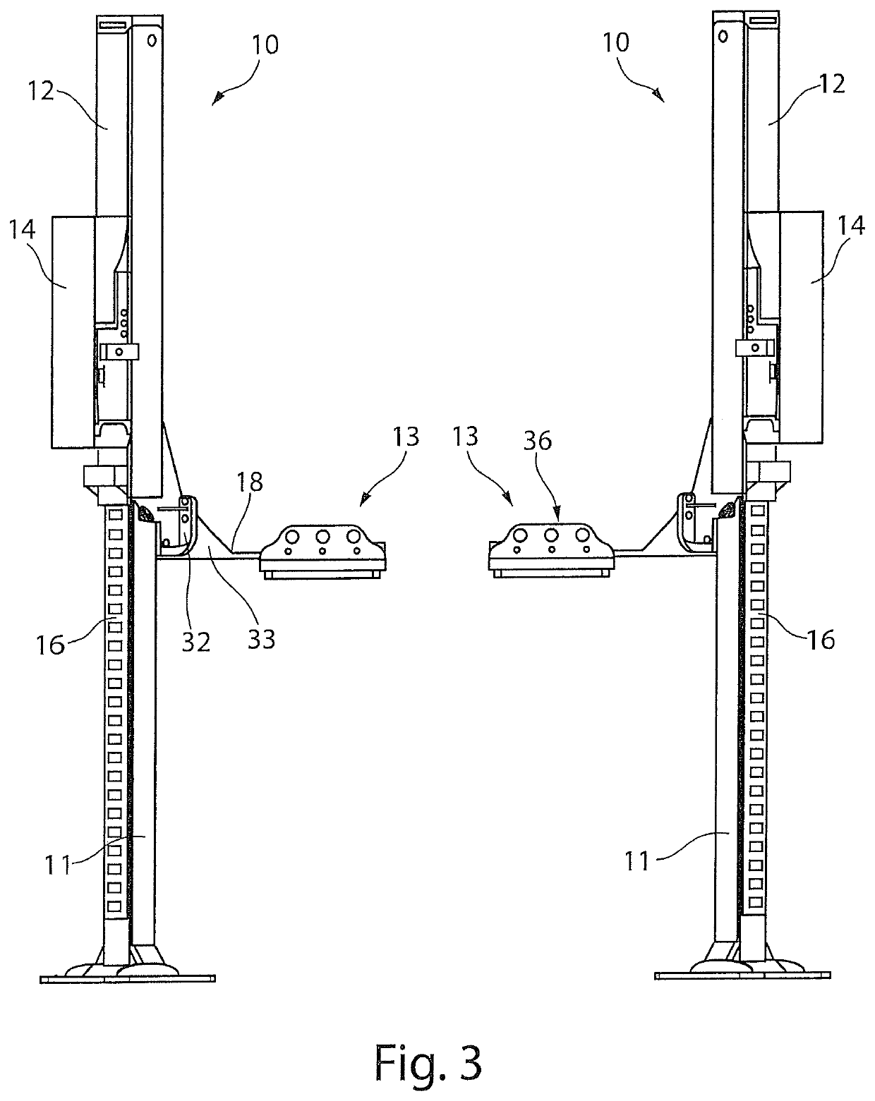
[0040]FIG. 1 shows a perspective view of a lifting platform 9 in which, for example, four lifting devices 10 are allocated to each other for the formation of a four-column lifting platform. A support 12 is arranged on the lifting column 11 of each lifting device 10. The support 12 is guided by a guide 16 and said support 12 is receiving a load receiver 13. A drive device 14 is provided on each support 12, by means of which the support 12 is able to be lifted and lowered vertically along the lifting column 11. The lifting devices 10 are arranged with respect to each other such that the load receivers 13 each receive a wheel or twin wheel, i.e. a dual wheel, of a vehicle and are able to be driven over by the vehicle.

[0041]The load receivers 13 comprise for example a planar, rectangular or quadratic receiving surfaces 15. A holding arm 18 is arranged in a corner region or lateral to each of the receiving surface 15 for connecting the load receiver 13 with the lifting column 11. The rec...


PUM


Abstract

A lifting device, in particular for lifting and lowering loads, vehicles or similar, having a vertical lifting column, having a support arranged on the lifting column, which is guided by a guide on the lifting column and is able to be driven vertically along the lifting column, having a drive device for lifting and lowering the support and a load receiver arranged on the support, wherein the load receiver is able to be driven over and has a drive-on region, a support region and a drive-off region which are arranged in a row along a mutual axis in the drive-over direction and the load receiver has a holding arm outside of the support region and outside of the drive-over direction of the drive-on region or drive-off region.

Description

RELATED APPLICATION DATA[0001]This application claims priority of German Patent Application No. 20 2014 103 785.3 filed Aug. 14, 2014, which is hereby incorporated herein by reference in its entirety.FIELD OF INVENTION[0002]The invention relates to a lifting device, in particular to lift and lower loads, vehicles or similar as well as lifting platforms consisting of lifting devices.BACKGROUND[0003]A column lifting platform, in particular a four-column lifting platform, for motor vehicles is known from DE 80 24 326 U1, in which each two lifting columns are arranged to lie opposite each other and a continuous drive rail to receive a vehicle is arranged on each two lifting columns which is able to be lifted and lowered by a lifting device.[0004]This column lifting platform has the disadvantage that a vehicle which is situated on the lifting platform for maintenance or assembly purposes is not freely accessible from all sides. On the one hand, the continuous drive rails cover a part of ...

Claims


Application Information

Patent Timeline
Patent Type & Authority Patents(United States)
IPC IPC(8): B66F3/00B66F3/46B66F7/02B66F7/28
CPCB66F7/28B66F3/46B66F3/00B66F7/02
Inventor BENZ, DIETER
Owner FINKBEINER GERHARD
Why Eureka
Try Eureka