Combination hoisting mounting method of continuous casting ladle turret

An installation method and combined hoisting technology used in transportation and packaging, load hoisting elements, etc.

Active Publication Date: 2017-06-20
CHINA MCC17 GRP
View PDF5 Cites 11 Cited by
  • Summary
  • Abstract
  • Description
  • Claims
  • Application Information

AI Technical Summary

Problems solved by technology

[0002] The ladle turret is the most common and most commonly used key mechanical equipment for ladle casting in the existing continuous casting production. The ladle turret is set above the casting position of the continuous casting machine and is a transfer equipment connecting molten steel receiving and casting; The ladle turret consists of six parts: base, slewing arm, driving device, slewing support, accident drive control system, lubrication system and anchors. Since it is located in the middle between the molten steel receiving span and the casting span, the receiving span cannot be used directly. O

Method used


Image

  • Combination hoisting mounting method of continuous casting ladle turret
  • Combination hoisting mounting method of continuous casting ladle turret
  • Combination hoisting mounting method of continuous casting ladle turret

Examples


Embodiment Construction

[0042] A combined hoisting and installation method for a continuous casting ladle rotary table proposed by the present invention was used in a steel mill’s four-steel rolling supporting continuous casting project in 2012 for the installation of a 300t ladle rotary table. The maximum ladle rotary table can hold up a total of 900t of heavy objects, the weight of a single piece of equipment is 334t, the receiving span of the plant is installed with a 500-ton crane, the casting span of the plant is installed with a 170-ton crane, and the construction steps for hoisting the continuous casting ladle turret into place are as follows:

[0043] Step 1. Fixture setting and anchor installation:

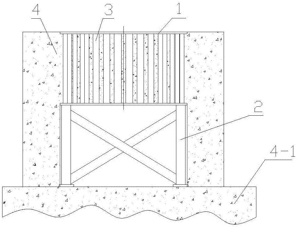
[0044] ①As attached figure 1 As shown in the figure, make the fixing frame (2) of the anchor first. After the production is completed, hoist the fixing frame (2) to the concrete platform (4-1), and align the upper surface of the fixing frame (2) so that it meets the requirements of the anchor. ...


PUM

PropertyMeasurementUnit
Thicknessaaaaaaaaaa
Lengthaaaaaaaaaa
Widthaaaaaaaaaa

Abstract

The invention belongs to a building construction method, and discloses a combination hoisting mounting method of a continuous casting ladle turret. The combination hoisting mounting method is characterized in that by employing the advantage that the ground in a factory building is wide, a part of components of the continuous casting ladle turret are assembled on the ground off-line, the components of the continuous casting ladle turret are transferred by adopting a sliding device, and are hung by a shoulder pole for hoisting, concrete is prevented from leaking into sleeves of foundation bolts by adopting an anti-leakage device, and a travelling crane of a molten steel receiving bay and a travelling crane of a casting bay that are arranged in the factory building are used jointly to hoist the various components of the continuous casting ladle turret in position. The combination hoisting mounting method comprises the following steps: one, a fixing bracket is arranged and anchor pieces are mounted; two, slurry of a foundation seat is prepared, and the sliding device is arranged; three, a base of the continuous casting ladle turret is hoisted; four, a revolving body is mounted; five, an upper part revolving support body is assembled and mounted; and six, accessories are mounted. The combination hoisting mounting method is fast in progress and high in precision, the construction efficiency is improved, and the construction cost is reduced.

Description

technical field [0001] The invention belongs to a building construction method, and in particular relates to an installation method of a continuous casting ladle turret. Background technique [0002] The ladle turret is the most common and most commonly used key mechanical equipment for ladle casting in the existing continuous casting production. The ladle turret is set above the casting position of the continuous casting machine and is a transfer equipment connecting molten steel receiving and casting; The ladle turret consists of six parts: base, slewing arm, driving device, slewing support, accident drive control system, lubrication system and anchors. Since it is located in the middle between the molten steel receiving span and the casting span, the receiving span cannot be used directly. Or the independent hoisting of the crane in the casting cross-factory, how to use the most convenient and reasonable combined hoisting method to install the ladle turret in place is the...

Claims


Application Information

Patent Timeline
IPC IPC(8): B66C13/04
CPCB66C13/04
Inventor 孔炯周金龙施光涛金仁才徐峥张杰
Owner CHINA MCC17 GRP
Why Eureka
Try Eureka