scroll compressor

A scroll compressor and scroll technology are applied in the field of scroll compressors to achieve the effects of reducing the rotating end plate, reducing the outer diameter and increasing the compression ratio

Active Publication Date: 2020-12-25
VALEO JAPAN CO LTD
View PDF9 Cites 0 Cited by
  • Summary
  • Abstract
  • Description
  • Claims
  • Application Information

AI Technical Summary

Problems solved by technology

like Image 6 As shown in (b), if the center of the base circle of the orbiting scroll 32 is deviated from the driving center axis α so that the center of gravity of the orbiting scroll 30 coincides with the driving center axis α, although the center of gravity due to the deviation of the center of gravity The torque is improved, but there is a disadvantage that the rotation torque of the orbiting scroll accompanied by the compression reaction force reverses at a specific phase during one rotation

Method used


Image

  • scroll compressor
  • scroll compressor
  • scroll compressor

Examples


Embodiment Construction

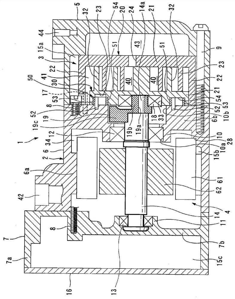
[0040] Below, while referring to the attached Figure 1 A configuration example of the scroll compressor of the present invention will be described.

[0041] exist figure 1 Among them, the scroll compressor 1 is an electric type compressor suitable for a refrigeration cycle using refrigerant as a working fluid, and a compression mechanism 3 is arranged on the right side of the figure in a housing 2 made of aluminum alloy. A motor 4 for driving the compression mechanism 3 is disposed on the left side in the figure. In addition, in figure 1 In the figure, let the left side in the figure be the front of the compressor 1, and let the right side in the figure be the rear of the compressor 1.

[0042] The casing 2 has a compression mechanism storage case member 5 that houses the compression mechanism 3 , a motor storage case member 6 that houses a motor 4 that drives the compression mechanism 3 , and houses an inverter device (not shown) that drives and controls the motor 4 . ...


PUM


Abstract

Provided is a scroll compressor comprising a rotation prevention mechanism constituted by disposing a plurality of rotation prevention parts in the circumferential direction so that each rotation prevention part engages, either directly or via a ring member, a circular recess (54) formed on the back surface of a turning end plate (31) of a turning scroll (30) and a pin that is provided to project from a housing wall that opposes the back surface of the turning end plate (31), wherein: a center-of-gravity adjustment recess (55) is formed in a range that does not reach the outer periphery of the turning end plate (31) of the turning scroll (30) between adjacent circular recesses (54) of the turning end plate (31); and the center-of-gravity adjustment recess (55) may be provided in a region corresponding to a winding end side of a turning lap (32) of the turning end plate (31).

Description

technical field [0001] The present invention relates to a scroll compressor, which uses a mechanism for engaging a pin fixed to a housing directly or via a ring in a circular recess provided on a rotating scroll as an anti-rotation mechanism. In particular, the present invention relates to a A scroll compressor capable of adjusting the position of the center of gravity of a revolving scroll and preventing reversal of self-rotation torque. Background technique [0002] A scroll compressor generally has a fixed scroll including a fixed end plate supported by the housing so that it cannot rotate relative to the housing, and a spiral fixed scroll vertically provided on the fixed end plate. Teeth: an orbiting scroll including a rotating end plate rotatably attached to an eccentric shaft provided at one end of a drive shaft, and a spiral-shaped orbiting wrap erected on the rotating end plate. The fixed scroll and the orbiting scroll are arranged in the housing in a state where th...

Claims


Application Information

Patent Timeline
Patent Type & Authority Patents(China)
IPC IPC(8): F04C18/02
CPCF04C18/02
Inventor 出口裕展A.贝莱特
Owner VALEO JAPAN CO LTD
Why Eureka
Try Eureka