Water flow garbage collecting structure of small-size water channel

A technology of garbage collection and water channel, applied in the field of water channel, can solve the problems such as the inability of the garbage collection device to facilitate the flow of water, the inconvenience of the use of the garbage collection device, the uncontrollable flow velocity of the water flow in the water channel, etc. The effect of stability

Inactive Publication Date: 2019-04-19
陈美容
View PDF1 Cites 0 Cited by
  • Summary
  • Abstract
  • Description
  • Claims
  • Application Information

AI Technical Summary

Problems solved by technology

[0008] In order to solve the above-mentioned technical problems, the present invention provides a small water canal garbage collection structure to solve the problem that the flow velocity of the water flow in the canal cannot be controlled when the existing canal is draining, and the existing canal garbage collection device can only be used simply. The water flow collects the garbage, so that the existing garbage collection device can only collect a part of the garbage, so that the existing garbage collection device is not convenient to use, because the existing garbage collection device needs to be installed inside the water channel when collecting garbage, and because of The size of the canal is limited, so that the existing garbage collection device cannot facilitate the flow of water, and because the device is in the water for a long time, it is easy to accumulate a large amount of dirt on the surface of the existing garbage collection device after long-term use, and because of the high water pressure. The existing garbage collection device is not convenient for users to quickly collect and clean up the garbage collected in the water

Method used


Image

  • Water flow garbage collecting structure of small-size water channel
  • Water flow garbage collecting structure of small-size water channel
  • Water flow garbage collecting structure of small-size water channel

Examples


Embodiment

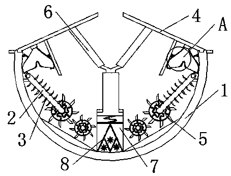
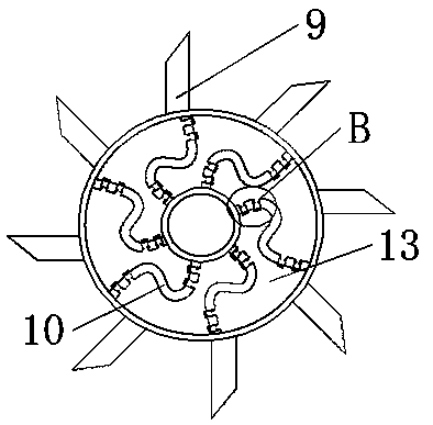
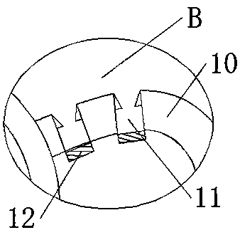
[0029] Embodiment: A small water canal water flow garbage collection structure, including a water canal 1, conveying crawlers 2 are provided on both sides inside the canal 1, fixed hooks 3 are evenly distributed on the outside of the conveying crawler 2, and bearings 5 ​​are rotated on one side of the conveying crawler 2 , the outer side of the bearing 5 is provided with a tooth piece 9, the inside of the bearing 5 is distributed with a connecting rod 10, the outer side of the connecting rod 10 runs through a water channel 13, the inside of the connecting rod 10 runs through a water port 11, and one side of the water port 11 is movable There is a movable cover 12, the other side of the conveying track 2 corresponds to a collection bag 15, the inside of the collection bag 15 has an inlet 16, one side of the collection bag 15 is nested with a fixed plate 17, and the upper end of the collection bag 15 is movable A movable plate 4 is nested, and one end of the movable plate 4 is el...


PUM

PropertyMeasurementUnit
Diameteraaaaaaaaaa

Abstract

The invention provides a water flow garbage collecting structure of a small-size water channel. The water flow garbage collecting structure of the small-size water channel comprises the water channel.Two sides of the interior of the water channel are provided with a conveying track. Fixing hooks are uniformly distributed at the outer side of the conveying track. One side of the conveying track isrotatably provided with a bearing. The outer side of the bearing is provided with a tooth plate. A connecting rod is distributed in the bearing. The outer side of the connecting rod is throughout provided with a water passage. The interior of the connecting rod is throughout provided with a water through port. Through installing the connecting rod, a water flow is avoided driving the bearing to be rotated through a moveable cover in the connecting rod while the water flow is anticlockwise flowed, and the bearing is avoided driving garbage to be anticlockwise rotated through the connecting rodwhile the bearing is anticlockwise rotated, so the bearing can drive the garbage to be clockwise rotated, a situation that the garage is driven to be flowed away from the interior of the water channel because of anticlockwise rotation of the bearing is avoided, and the garbage can be driven to be conveyed above the conveying track, thereby the garbage can be rapidly collected.

Description

technical field [0001] The invention belongs to the technical field of water channels, and in particular relates to a garbage collection structure. Background technique [0002] The canal is a building structure that uses water and stores water during agricultural planting. The width of the canal is 1.5-2 meters. Due to the wide canal and the fact that there are more domestic waste generated by human beings, a certain amount of garbage is easy to accumulate inside the canal, making The inside of the canal is easily blocked during agricultural planting and irrigation, so that the inside of the canal needs to be manually cleaned before agricultural planting. [0003] For example, the patent with application number CN201711411686.3 discloses a garbage barrier net for irrigation canals. The technical problem to be solved by this invention is to provide a garbage barrier for irrigation canals that can be easily installed and disassembled and effectively prevent garbage from enter...

Claims


Application Information

Patent Timeline
IPC IPC(8): E02B13/00E02B5/08
CPCE02B13/00E02B5/085
Inventor 陈美容
Owner 陈美容
Why Eureka
Try Eureka