
Shale anisotropic rock physical model modeling method

A petrophysical model and anisotropy technology, applied in the field of petrophysical model modeling, can solve the problems of not considering the microstructure characteristics of shale, not considering the orientation of clay minerals, etc.

Active Publication Date: 2019-04-19
CHINA PETROLEUM & CHEM CORP +1
View PDF3 Cites 23 Cited by
  • Summary
  • Abstract
  • Description
  • Claims
  • Application Information

AI Technical Summary

Problems solved by technology

However, most domestic shale petrophysical models do not consider the orientation of clay minerals, adding clay minerals to the model as an isotropic medium, and do not consider the microstructural characteristics of shale.

Method used


Image

  • Shale anisotropic rock physical model modeling method
  • Shale anisotropic rock physical model modeling method
  • Shale anisotropic rock physical model modeling method

Examples


Embodiment 1

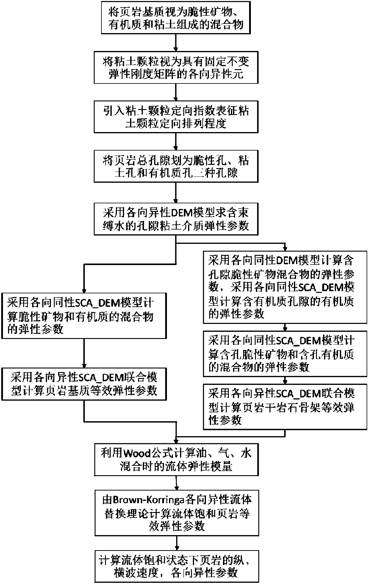
[0078] figure 2 A schematic modeling diagram of a method for modeling an anisotropic petrophysical model of shale according to an embodiment of the present invention is shown.

[0079] like figure 2 As shown, 1) First, the elastic properties of brittle minerals are simulated by the Hashin-Shtrikman boundary model in the case of isotropic mixing. Since brittle minerals such as quartz, feldspar, calcite, dolomite, and pyrite can all be regarded as rigid minerals, The elastic properties are relatively close, and this model can be used for mixing;

[0080] 2) Addition of brittle mineral pores: The brittle minerals in the Longmaxi Formation shale are distributed with intergranular pores and intragranular dissolution pores, and most of them are disconnected pores. The pore diameter and aspect ratio of such pores are usually large, but the content is small. Therefore, the isotropic differential equivalent medium model (isotropic DEM model) can be added to the brittle mineral mixt...

Embodiment 2

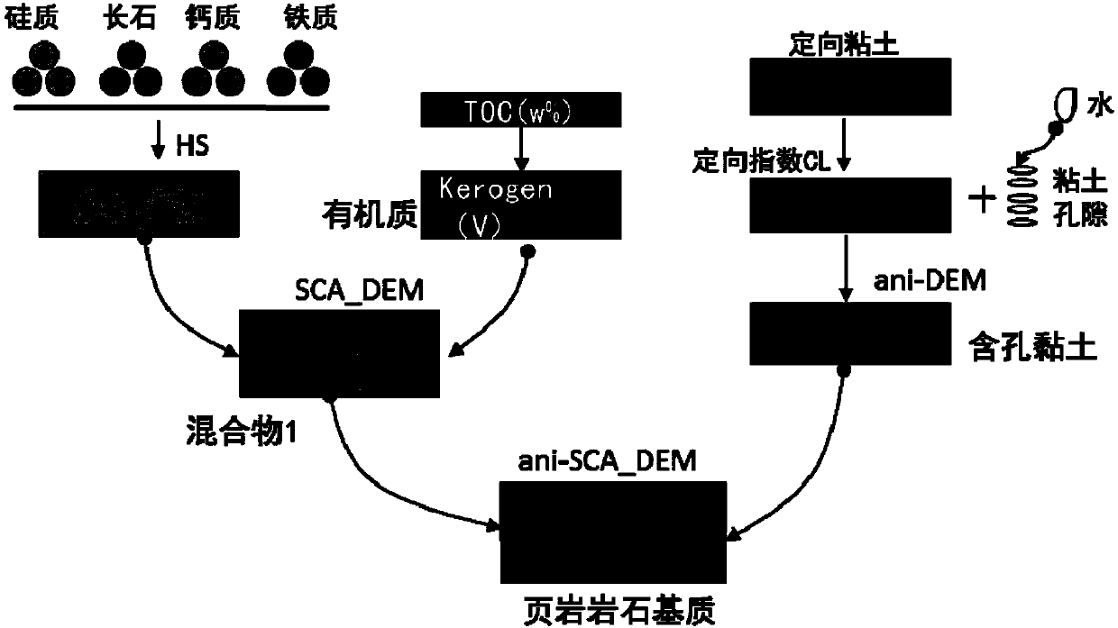
[0095] This embodiment specifically illustrates the shale anisotropic rock physical model modeling method of the present invention through three major steps of calculation of shale rock matrix parameters, calculation of shale dry rock skeleton parameters and calculation of shale saturated rock parameters.

[0096] image 3 A schematic diagram of obtaining shale rock matrix parameters in the method for modeling an anisotropic rock physical model of shale according to an embodiment of the present invention is shown. Figure 4 It shows a schematic diagram of obtaining shale dry rock skeleton parameters in the shale anisotropic petrophysical model modeling method according to an embodiment of the present invention. Figure 5 It shows a schematic diagram of obtaining shale saturated rock parameters in the shale anisotropic rock physical model modeling method according to an embodiment of the present invention. Among them, HS represents the Hashin-Shtrikman boundary theory model, a...


PUM


Abstract

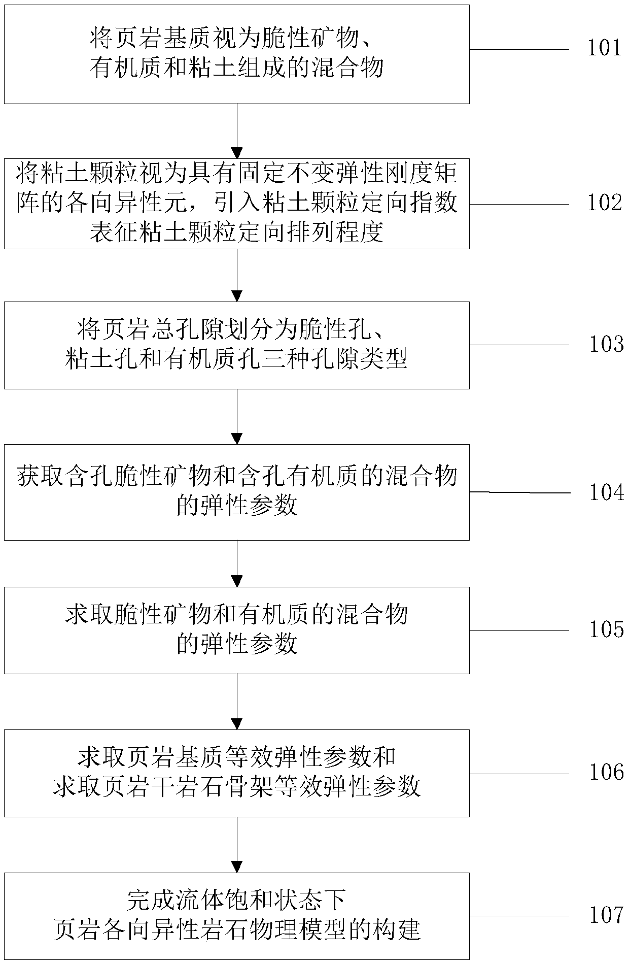
The invention discloses a shale anisotropic rock physical model modeling method. The shale anisotropic rock physical model modeling method comprises the steps that regarding a shale matrix as a mixture composed of brittle minerals, organic matters and clay; regarding clay particles as anisotropic elements with a fixed invariant elastic stiffness matrix, and introducing clay particle orientation indexes to represent the orientation arrangement degree of the clay particles; dividing shale total pores into brittle pores, clay pores and organic matter pores; obtaining elastic parameters of a mixture of porous brittle minerals and porous organic matters; calculating elastic parameters of the mixture of the brittle minerals and the organic matters; calculating elastic parameters of the pore claymedium containing bound water; solving equivalent elastic parameters of the shale matrix and a shale dry rock framework; and obtaining fluid saturated shale equivalent elastic parameters based on theshale matrix and the shale dry rock skeleton equivalent elastic parameters, and completing the construction of the shale anisotropic rock physical model in the fluid saturated state. According to themethod, the longitudinal and transverse wave velocity and anisotropy parameters of the shale can be predicted more accurately.

Description

technical field [0001] The invention belongs to the field of petrophysical model modeling, and more specifically relates to a shale anisotropic rock physical model modeling method. Background technique [0002] The microstructure of shale is relatively complex, and there are various factors affecting the elastic properties of shale. Complex mineral components, organic matter, directional arrangement of clay particles, and the development of micro-cracks will all affect the elastic properties of shale. Shale has typical strong anisotropy characteristics, which are difficult problems not encountered in conventional reservoir rock physics modeling. At present, there is no effective petrophysical model modeling method to describe the elastic properties of shale. [0003] Based on the research on the microstructure and anisotropy characteristics of shale, it is shown that the clay mineral content and its directional arrangement are the main factors for its anisotropy, such as th...

Claims


Application Information

Patent Timeline
IPC IPC(8): G01V99/00
CPCG01V20/00
Inventor 刘卫华
Owner CHINA PETROLEUM & CHEM CORP
Learn More