A new gravure printing machine

A kind of gravure printing machine, a new type of technology, applied in the direction of gravure rotary printing machine, printing machine, rotary printing machine, etc., can solve the problems of low installation accuracy, different sizes of paper guide shafts, and mechanical transmission technology not suitable for modern production, etc., to achieve elimination External force, weakening the effect of external force

Active Publication Date: 2020-08-11
河南省邮电科技有限公司
View PDF4 Cites 0 Cited by
  • Summary
  • Abstract
  • Description
  • Claims
  • Application Information

AI Technical Summary

Problems solved by technology

However, with the increasing development and improvement of electronic technology, the traditional mechanical transmission technology is becoming less and less suitable for the needs of modern production.
When changing products, it is necessary to replace gears, paper guide shafts, etc., which is a waste of time. Second, because the sizes of various products sometimes vary very little, the size of the gears is easy to identify, and the diameter of the paper guide shaft is difficult to distinguish with the naked eye.
In the unwinding traction structure of the gravure printing machine, due to the small diameter of the traction rubber roller, various supporting components are usually added, and the design of these components is often lacking, resulting in low installation accuracy, difficulty in installation and disassembly, and faster wear of parts, etc. question
For modern production with higher and higher precision requirements, it is difficult to meet the control requirements

Method used


Image

  • A new gravure printing machine

Examples


Embodiment 1

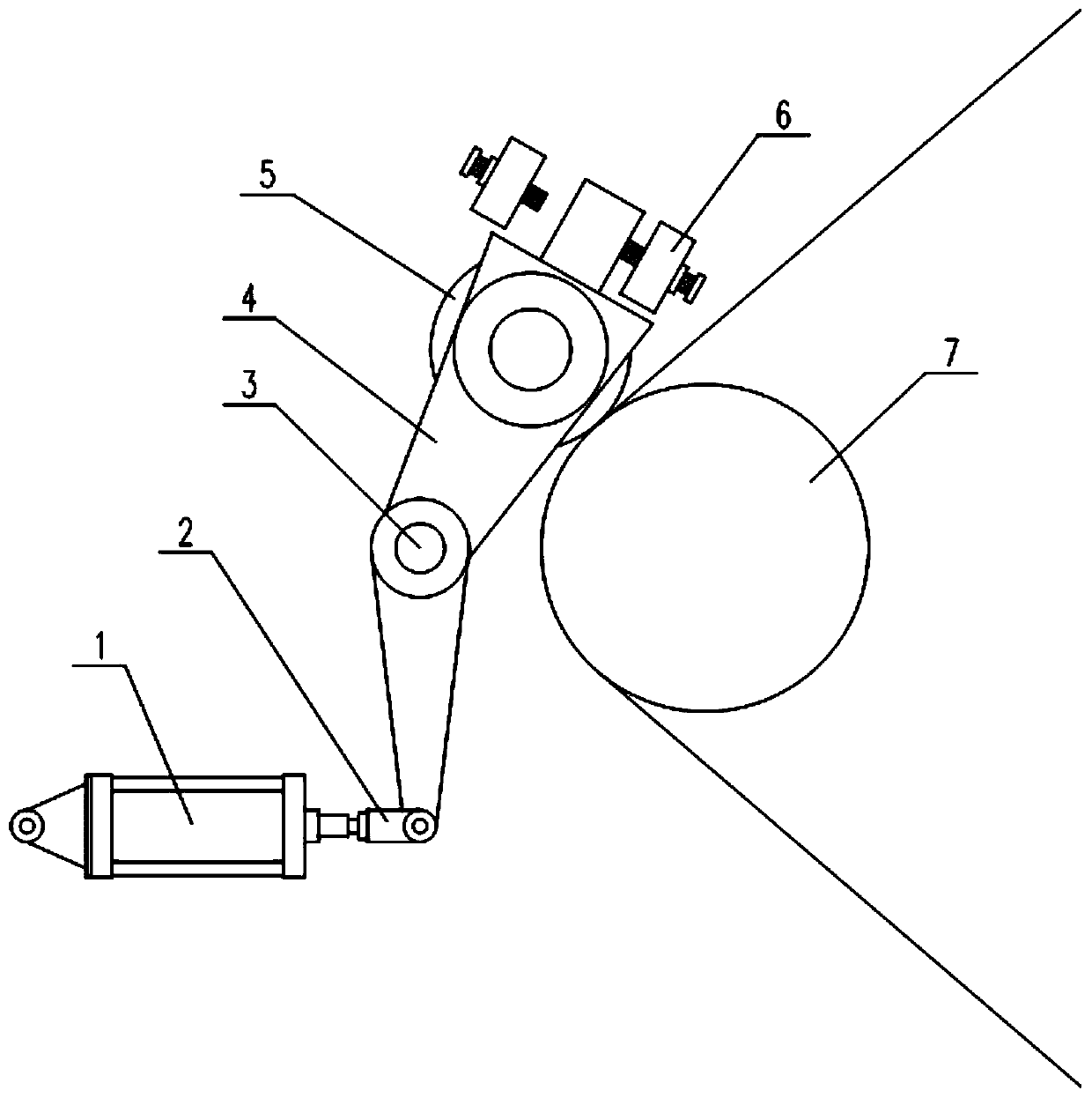
[0026] A new type of gravure printing machine provided by the preferred embodiment of the present invention includes a buffer structure 1 and a force transmission structure 2; the buffer structure 1 includes a No. 1 runner and a No. 1 transmission block; The shaft is fixedly connected; the outside of the No. 1 runner is connected to one side of the No. 1 transmission block; the other side of the No. 1 transmission block is connected to one end of the spring; the other end of the spring is connected to one side of the force transmission structure 2; the force transmission Structure 2 includes the No. 2 transmission block and the No. 1 runner; one side of the No. 2 transmission block is connected with the other end of the spring, and the other side is connected with the No. 1 runner; the geometric center point of the No. 1 runner, the No. 1 transmission block The line between the geometric center point of the drive block and the geometric center point of the second transmission b...

Embodiment 2

[0030] In this embodiment, on the basis of Embodiment 1, preferably, the diameter of the No. 1 runner is smaller than the diameter of the No. 2 runner; the diameter of the No. 2 runner is smaller than the diameter of the No. 3 runner 5; the diameter of the No. 3 runner 5 Smaller than the diameter of the drum 7, it is convenient for the transmission and weakening of the external force.

[0031] Preferably, the diameter of the No. 1 rotating shaft is smaller than that of the No. 2 rotating shaft; the diameter of the No. 2 rotating shaft is smaller than the diameter of the No. 3 rotating shaft, so as to better weaken the external force.

[0032] Preferably, the linkage rod is perpendicular to the horizontal plane, so as to fully transmit the external force to the stressed structure.

[0033] Preferably, the included angle between the linkage plate 4 and the horizontal plane is 60°, so that after the No. 3 roller 5 is stressed, part of the external force is applied to the linkage ...


PUM


Abstract

The invention discloses a novel gravure press and a processing method thereof, and belongs to the field of printing equipment. The novel gravure press comprises a buffer structure and a force transmission structure; the buffer structure is connected with the force transmission structure through a spring; the force transmission structure is connected with a No.2 rotating wheel through a linkage rod; the No.2 rotating wheel is connected with a No.3 rotating wheel through a linkage plate; the linkage plate is provided with a bolt connector; and the outer side of the No.3 rotating wheel is in contact with the outer side of a roller. According to the novel gravure press, through the No.3 rotating wheel, the No.2 rotating wheel, the force transmission structure and the buffer structure, force generated during rotation of the roller can be reduced, and the buffer effect is achieved; and excessive damage to parts is avoided.

Description

technical field [0001] The invention belongs to the field of printing equipment and relates to a novel gravure printing machine. Background technique [0002] The coordination between the unwinding unit, tension control unit, printing unit and die-cutting unit in traditional gravure printing machines is mainly realized by mechanical components, such as gears, shafts, etc. The application of these mechanical accessories was of great positive significance at that time. However, with the increasing development and improvement of electronic technology, the traditional mechanical transmission technology has become less and less suitable for the needs of modern production. When changing products, it is necessary to replace gears, paper guide shafts, etc., which is a waste of time. Second, because the size of various products sometimes varies very little, the size of the gears is easy to identify, and the diameter of the paper guide shaft is difficult to distinguish with the naked...

Claims


Application Information

Patent Timeline
Patent Type & Authority Patents(China)
IPC IPC(8): B41F9/00
CPCB41F9/00
Inventor 张蕾燕其廷
Owner 河南省邮电科技有限公司
Why Eureka
Try Eureka