A multi-task control computer switching device

A switching device and computer technology, applied in computing, input/output of user/computer interaction, input/output process of data processing, etc., can solve problems such as defects in information security protection of multi-computer switchers, and achieve information security protection Defects, the effect of ensuring information security

Pending Publication Date: 2019-04-23
熊文昕
View PDF0 Cites 3 Cited by
  • Summary
  • Abstract
  • Description
  • Claims
  • Application Information

AI Technical Summary

Problems solved by technology

[0004] The purpose of the present invention is to solve the problem of the defect of information security protection of the existing multi-computer switcher, and propose a computer switching device with multi-task control

Method used


Image

  • A multi-task control computer switching device
  • A multi-task control computer switching device
  • A multi-task control computer switching device

Examples


Embodiment 1

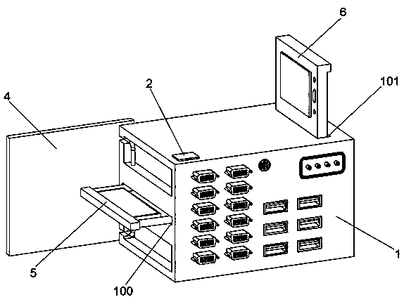
[0039] A computer switching device for multi-task control, including an outer casing 1 and a fingerprint identification system 2, and also includes:

[0040] A fingerprint recognition system 2, the fingerprint recognition system 2 is arranged on the upper side of the outer casing 1, and the fingerprint recognition system 2 is used to control the transmission mechanism 3, the box door assembly 4, the keyboard assembly 5 and the display assembly 6;

[0041] The transmission mechanism 3, the transmission mechanism 3 is arranged on the left side inside the outer casing 1, and the transmission mechanism 3 is used to drive the box door assembly 4, the keyboard assembly 5 and the display assembly 6;

[0042] The box door assembly 4, the box door assembly 4 is arranged on the front end of the outer casing 1, and the box door assembly 4 is used to protect the outer casing 1;

[0043] A keyboard assembly 5, the keyboard assembly 5 is arranged inside the front end of the outer casing 1, ...

Embodiment 2

[0050] Embodiment 2: the difference based on Embodiment 1 is;

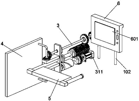
[0051] The transmission mechanism 3 includes a fixed part 300, a rotating shaft A301, a guide block 302, a helical gear A303, a rotating shaft B304, a cylindrical cam 305, a helical gear B306, a rotating shaft C307, a helical gear C308, a bevel gear A309, and a bevel gear B310;

[0052] The fixing part 300 is fixed inside the outer casing 1, the middle part of the fixing part 300 is movably connected with a rotating shaft A301, and the rotating shaft A301 is fixedly connected with the keyboard assembly 5, and the outside of the middle part of the rotating shaft A301 is movably connected with a guide block 302, and the rear end of the rotating shaft A301 is fixedly connected with a helical gear A303;

[0053] The lower part of the fixing piece 300 is rotationally connected with the front end of the rotating shaft B304, the outer front end of the rotating shaft B304 is fixedly connected with a cylindrical cam 305, th...

Embodiment 3

[0056] Embodiment 3: the difference based on Embodiment 1 and 2 is;

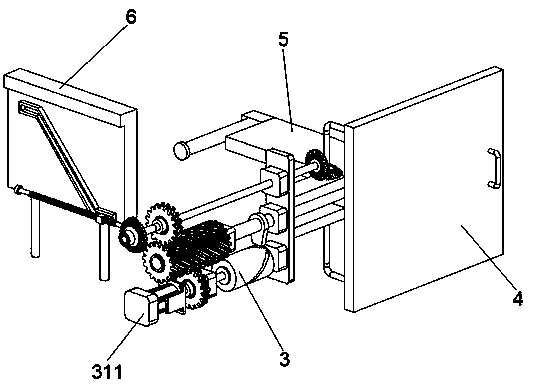
[0057] The box door assembly 4 includes a door body 400, an L-shaped connecting rod 401, a bevel gear C402 and a handle frame 403;

[0058] Two L-shaped connecting rods 401 are symmetrically welded on the inner rear end of the door body 400. The ends of the L-shaped connecting rods 401 are rotatably connected to the front end of the fixing part 300. The outer end of the upper L-shaped connecting rod 401 is fixedly provided with a bevel gear C402. The bevel gear C402 is meshed with the bevel gear A309 for transmission, and the outer end of the door body 400 is also fixedly provided with a handle frame 403 .

[0059] The keyboard assembly 5 includes a mounting frame 500, a keyboard 501, a limit rod 502 and a limit protrusion 503;

[0060] The outer side of the mounting frame 500 is slidingly connected to the inner wall of the keyboard storage groove 100 at the front end of the outer shell 1. The upper surface...


PUM


Abstract

The invention discloses a multi-task control computer switching device, and belongs to the field of computer management equipment. The multi-task control computer switching device comprises an outer shell and a fingerprint recognition system, and further comprises a transmission mechanism, a box door assembly, a keyboard assembly and a displayer assembly, and the transmission mechanism is electrically connected with the fingerprint recognition system. The fingerprint identification system is arranged on the top surface of the outer shell; by the fingerprint identification of a user, after theuse permission is determined, the micro motor controls the transmission mechanism to operate; and the transmission mechanism is used for driving the box door assembly, the keyboard assembly and the displayer assembly to be opened, so that the defect that an existing high-end multi-computer switcher lacks an information safety protection function is overcome, lawbreakers are prevented from using the high-end multi-computer switcher at will to control multiple computers to conduct illegal behaviors, and meanwhile the information safety of enterprises and companies is guaranteed.

Description

technical field [0001] The invention relates to the field of computer management equipment, in particular to a computer switching device for multi-task control. Background technique [0002] KVM is the abbreviation of Keyboard (keyboard), Video (monitor), and Mouse (mouse). The official name of KVM switch is multi-computer switch or KVM SWITCH. Simply put, a KVM switch allows system administrators to control the computer peripherals of multiple servers or computer hosts through a set of keyboards, monitors and mice, which means that only one person can interact with all computers, of course, at one time Can only interact with one. In addition to saving the overhead of multiple keyboards and monitors, a switcher can free up more desk space. KVM switches are usually used in networks and other server sites with multiple computers. In these cases, there are usually multiple computers but only one administrator or network administrator. Moreover, the development of KVM techno...

Claims


Application Information

Patent Timeline
Patent Type & Authority Applications(China)
IPC IPC(8): G06F3/038G06F3/02G06F3/14G07C9/00
CPCG06F3/038G06F3/02G06F3/14G07C9/00563
Inventor 熊文昕任剑岚
Owner 熊文昕
Why Eureka
Try Eureka